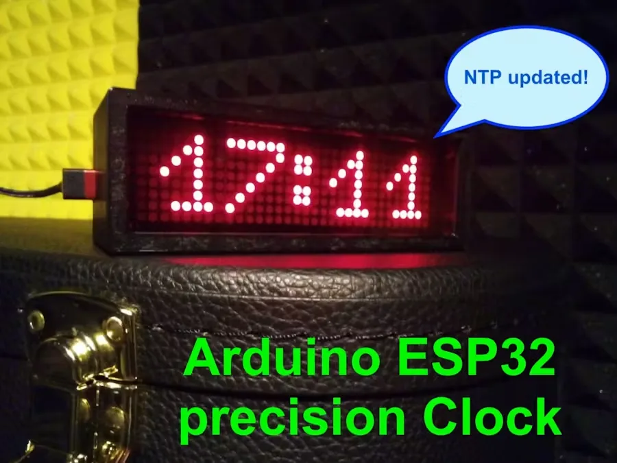
Arduino Nano ESP32 LED Matrix Clock with WiFi Time Sync
This project presents a digital clock built with an Arduino Nano ESP32 and an 8×32 LED matrix driven by a MAX7219 controller. The goal is a compact clock with clearly visible digits, moderate brightness, and precise time updates over WiFi. The system also supports manual configuration over Bluetooth BLE and is powered via USB-C.
Project architecture
The heart of the system is the Arduino Nano ESP32, chosen for its built-in WiFi, BLE, internal memory, USB-C port, and compact size. The display uses four 8×8 LED matrix modules, managed by the MAX7219 and powered at 5 volts. Since the microcontroller runs at 3.3 volts, the circuit includes a bidirectional level shifter to adapt the communication properly.
The project also integrates an LDR photoresistor for automatic brightness adjustment. In addition, there are three push buttons and an LED for manual time setting when WiFi is not available. The build also includes a dedicated PCB, a 3D-printed enclosure, screws, standoffs, a right-angle USB-C adapter, and a red plexiglass front panel.
Configuration and time synchronization
WiFi parameters and time zone are configured by entering Setup mode and connecting to the clock over Bluetooth. The system accepts text strings to set the network name, password, and time zone. The data is then saved to the internal EEPROM memory. If the network parameter is left empty, NTP over WiFi is skipped and the time must be set manually using the dedicated hour and minute buttons.
When a network is available, the clock syncs the time at power-on in about 30 seconds and then refreshes every hour. The code also handles DST correction for Central European summer time. Additionally, the state of the colon dots indicates whether a recent sync occurred or whether the time may be inaccurate or manually set.
Software and power consumption
Development was done using the Arduino Web Editor. The text notes that some parts of the code required specific adaptations, particularly for EEPROM handling and communication with the MAX7219 display. The LedControl library did not work directly on the Nano ESP32, so a synchronous serial transmission system was implemented using three digital pins with code embedded in the sketch.
Brightness ranges from 0 to 15, but the project recommends staying at level 5 or below to keep consumption within the typical USB power limit. The text reports approximate current draws of 75 mA at level 0, 245 mA at level 2, 525 mA at level 6, and 725 mA at level 10, with all 256 LEDs lit. The numeric font remains fully customizable by editing the matrices defined in the code.