LED Traffic Light Module for Arduino: Features, Wiring, and Testing
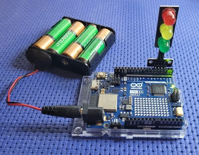
The LED traffic light module is a compact and straightforward solution for adding light signals to electronics projects. It integrates three separate LEDs – red, yellow, and green – on a single board, simplifying both wiring and development. It operates on a voltage between 3.3 V and 5 V, making it compatible with many prototyping platforms. Adrirobot used and reviewed it on his BLOG.
Module structure and electrical configuration
The module uses a common-cathode configuration. In practice, all the negative terminals of the LEDs converge on a single ground pin, while the positive terminals are controlled separately.
Each LED is associated with a dedicated resistor. This component is essential because it limits the current and protects the components. Specifically, the red LED uses a resistor of about 330 ohms, the yellow one 220 ohms, and the green one 470 ohms. As a result, each color can be driven in a stable and independent way.
The main connector has four pins: one for each LED and one for the common ground. This configuration allows a direct interface with the digital pins of a control board.
Wiring and control with a microcontroller
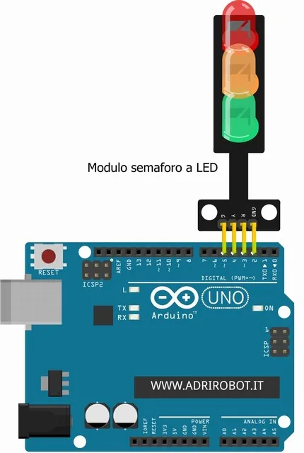
Wiring the module is simple and immediate. The three pins dedicated to the LEDs connect to the digital outputs of the microcontroller, while the GND pin goes to the system ground.
When the microcontroller sets a pin to HIGH, the corresponding LED turns on. Conversely, setting the pin to LOW turns the LED off. This behavior makes it easy to manage light sequences and signaling logic.
It is also possible to use a digital pin configured as a LOW output to simulate a ground, creating an alternative solution useful during prototyping.
Operation and test sequences
A typical configuration assigns the three LEDs to three distinct digital pins. Then, a simple program can activate the LEDs in sequence.
For example, each LED can blink for a set interval, with regular on and off cycles. After completing the sequence of the three colors, the system can introduce a pause and then repeat the cycle. This kind of test quickly verifies that the module works correctly.
Practical applications
The LED traffic light module is used in several areas. In particular, it fits well in educational settings, where it helps explain digital logic and output management.
It can also be used to simulate traffic systems or intersections, offering a concrete example of sequential control. In automation systems, it can indicate the state of a process: red for error, yellow for waiting, and green for active operation.
Other uses include device monitoring, managing queues or access, and integration into model-making or home automation projects. Thanks to its simplicity, the module suits many scenarios without requiring complex circuits.
Integration into electronics projects
Thanks to its compact structure and reduced wiring, the module integrates easily into prototypes and more advanced systems. In addition, the presence of the integrated resistors eliminates the need for extra components.
This approach reduces wiring errors and speeds up development. As a result, the module is a practical solution for anyone who wants to add clear and effective light signals to an electronics project.