Arduino UNO R4 WiFi: A Guide to Sensors and Displays
We bring the connections of the STEMMA QT/Qwiic connector available on the Arduino UNO R4 WiFi to the outside, using a board that can host I²C-Bus devices and can be daisy-chained with others of the same type.
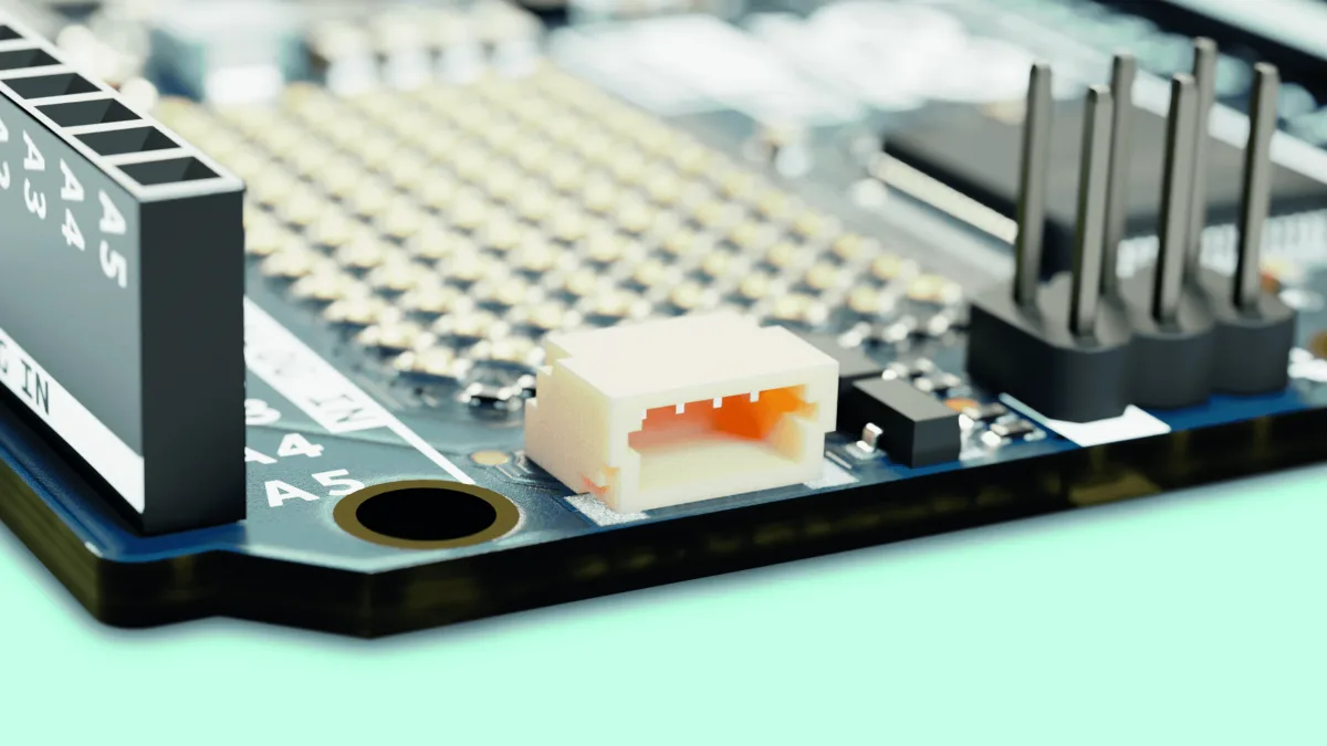
Among the new features introduced by the Arduino UNO R4, the WiFi version stands out with a small interface connector called STEMMA QT/Qwiic. For form-factor compatibility reasons, this connection did not find a place in the traditional headers compatible with UNO boards, but it is located on the left side of the ICSP.
The connector makes an I²C-Bus accessible according to the pinout shown in Fig. 1, which can be used to manage external devices such as displays, sensors, etc., as long as they support I²C communication.
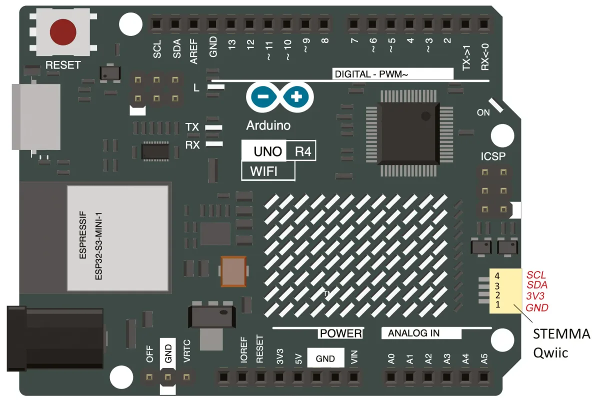
The SCL and SDA lines, unlike what happens in previous Arduino boards based on Atmel processors (where they were shared with pins A4 and A5 of the standard Arduino header), are connected to a second (secondary) I²C bus. In fact, the Renesas chip used in the R4 makes two distinct I²C buses available. The second one must be managed, however, by calling the specific object Wire1, as will be explained later in this article. The connection was introduced in the Arduino R4 (only in the WiFi version) to quickly connect Sparkfun standard breakout boards to it, since the connector used, a 4-pin single-in-line PCB connector, is the one adopted by Sparkfun boards. Qwiic is an ecosystem of breakout modules and development boards equipped with a so-called Qwiic connector, and it combines the flexibility of I²C with the ease of use of ready-made compatible cables available on the market, making it simple to manage a chain of I²C-Bus devices through a single cable. In practice, this means that wiring Qwiic devices is as simple as connecting them in series, and that’s it. To facilitate the connection and provide physical support for the breakout boards, instead of leaving them “flying,” we thought of designing and proposing a small adapter board that has two connectors compatible with the STEMMA QT/Qwiic standard, creating a pass-through connection that allows interfacing devices on the board itself, but also using the I²C bus to connect other devices. The I²C-Bus connections are distributed on our board in rows of pads where you can insert strips to connect and mechanically support breakout boards. Everything will be clearer by analyzing the project’s electrical schematic, which you can find on this page.
Electrical schematic
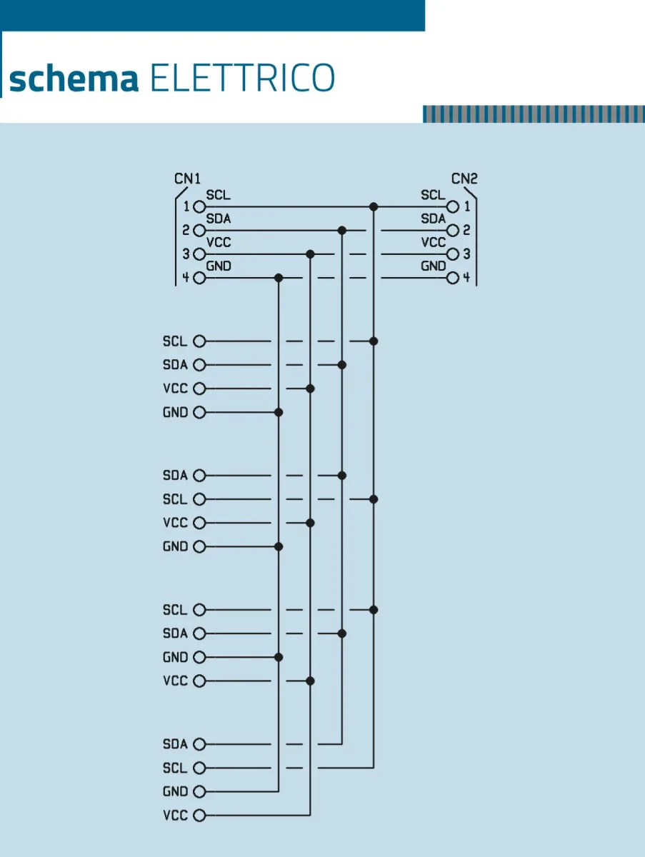
As you can see, it is something very simple, which in fact has no electronics but simply creates a series of electrical interconnections, making a pass-through I²C-Bus connection between input and output through the two 4-pin Sparkfun-type connectors, and which has four rows of four pads at 2.54 mm pitch, ready for soldering female strips or pin strips for sensors and various devices. Note that the layout on the printed circuit board provides that the rows of pads have contacts arranged differently from one side to the opposite one: we wanted this to allow mounting boards and especially displays (since the problem occurs, for example, with small OLEDs) that have a different arrangement of Vcc and GND, as well as SDA and SCL. Through the STEMMA QT/Qwiic connector, the power needed for the breakout boards to operate is taken from the Arduino UNO R4 board, thus achieving independent operation of the devices connected to Arduino. As you can see, the circuit is essential and basically only serves to carry connections. The nice thing is that having two JST connectors makes it possible to daisy-chain numerous I²C-Bus interface devices on multiple boards, since the one connected to the Arduino R4 can in turn be connected to a second board, the latter to a third, and so on, to host more elements. For the interconnection between the Arduino R4 and our board, and between multiple adapter boards, you can use a pre-wired cable with a 4-pin JST connector at each end, 1 mm pitch, available at Futura Elettronica. The adapter board we propose here can also be purchased ready-made from [Futura Elettronica](www.futurashop.it) with product code FT1732M.
Construction and use
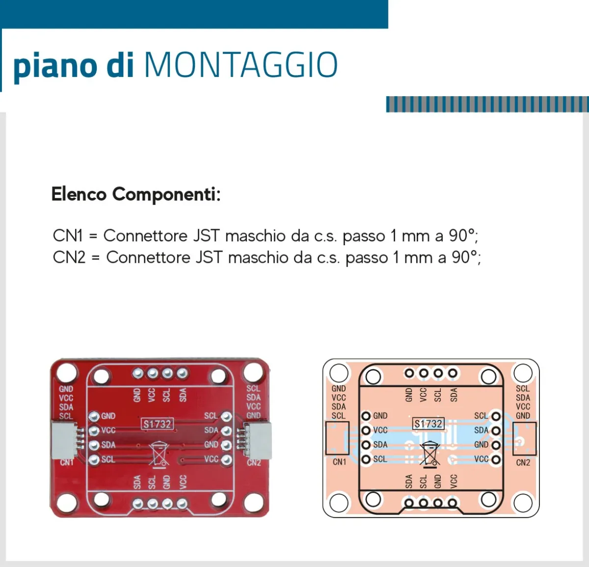
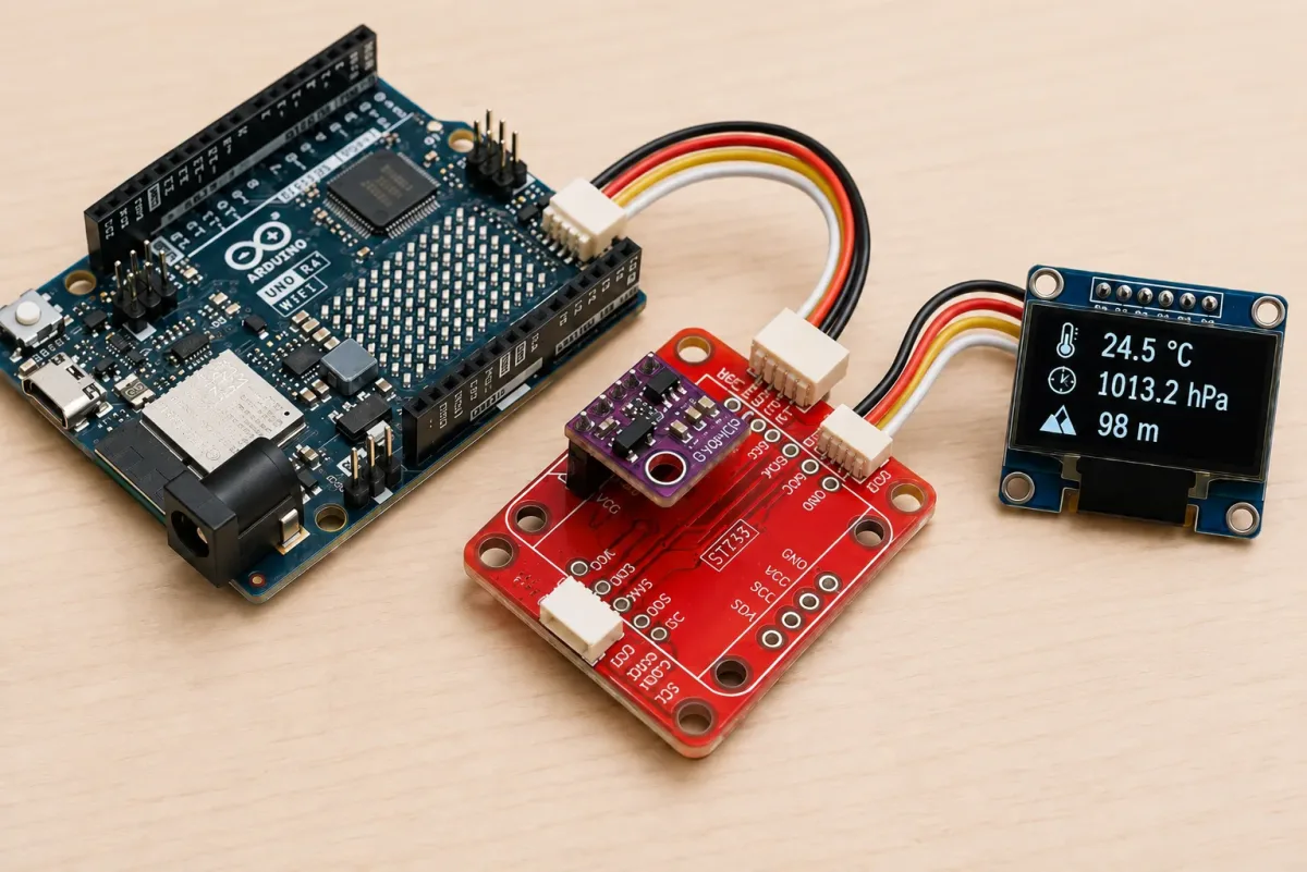
The small adapter board described here can be easily prepared by photoengraving once you have the two copper-side traces, however, given its really low cost, it is possible and convenient to buy it ready-made. To explain how to use it, we propose a basic application that involves acquiring information from a breakout board for barometric pressure and ambient temperature sensors, then displaying it on a small 0.96″ monochrome OLED display based on the SSD1306 controller; clearly, we are referring to two devices equipped with an I²C-Bus interface. The Arduino R4 WiFi connector to use is the one detailed in Fig. 2. To use a Bosch BME280 sensor on a breakout board with the Arduino R4 and the STEMMA standard, you must mount the small breakout board using the appropriate pin strips and following the intended orientation (Fig. 3 can help you, where you can also see in which position to mount it); be careful that if you do not respect the indicated position and orientation, the small board can be irreparably damaged.
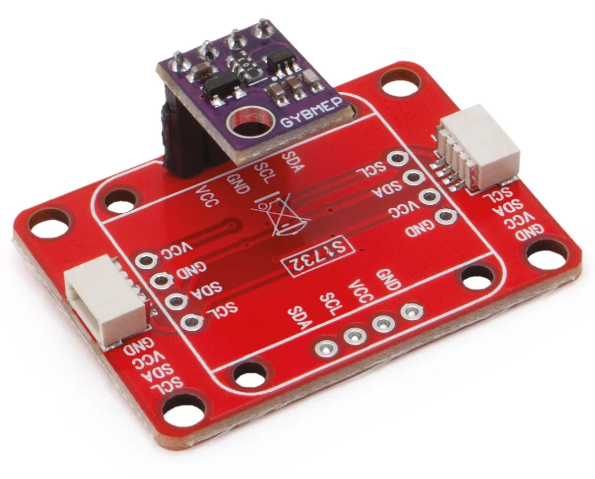
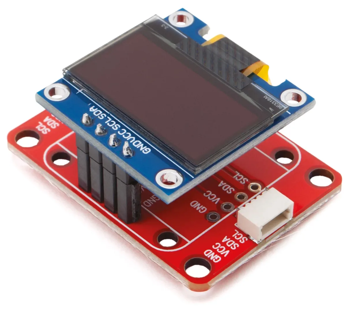
This is because, as mentioned, the rows of I²C-Bus pads inside the printed circuit board are arranged differently depending on which side they are on, to allow mounting all breakout boards available on the market, equipped with 2.54 mm pitch strip connections. On a second FT1732M adapter board, you must mount the small OLED display, which is a standard type and, more precisely, the one sold by Futura Elettronica with the code OLEDGVSCSD; the device must be applied as shown in Fig. 4 after soldering a 4-pin pin-strip to it and using the row of pads whose contacts are arranged as follows: GND, VCC, SCL, SDA.
To implement communication with the BME280 breakout, you must first load the Adafruit_BME280 library into the Arduino IDE; to do this, open the IDE, go to the Sketch menu, and issue the Include Library > Manage Libraries… command. At this point, search for “Adafruit BME280” in the search bar and install the corresponding library. Installation can also be done from a .zip file containing the library, using the appropriate menu command. Then, from the File menu, you can issue the Examples command and load the “BME280_I2C” example; once the sketch is displayed, load it onto the board (the IDE must already have the UNO R4 WiFi among the boards available in the Tools > Board… submenu) and run it, opening the Serial Monitor to view the pressure and temperature data read by the sensor. Note that the Arduino UNO R4 WiFi has two I²C buses and that the Qwiic connector is connected to the secondary one, so you must use Wire1. In most cases, you will be able to select the Wire1 object during library initialization with this code snippet:
Wire1.begin();
libraryName.begin( Wire1 );
Our test sketch
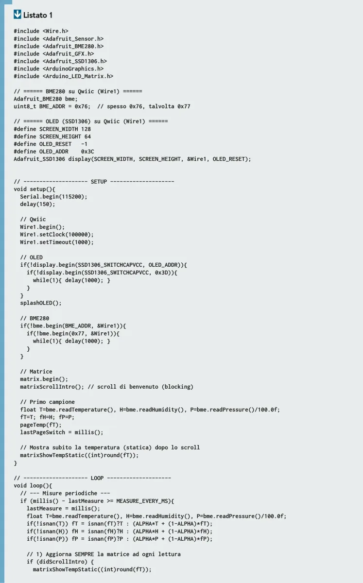
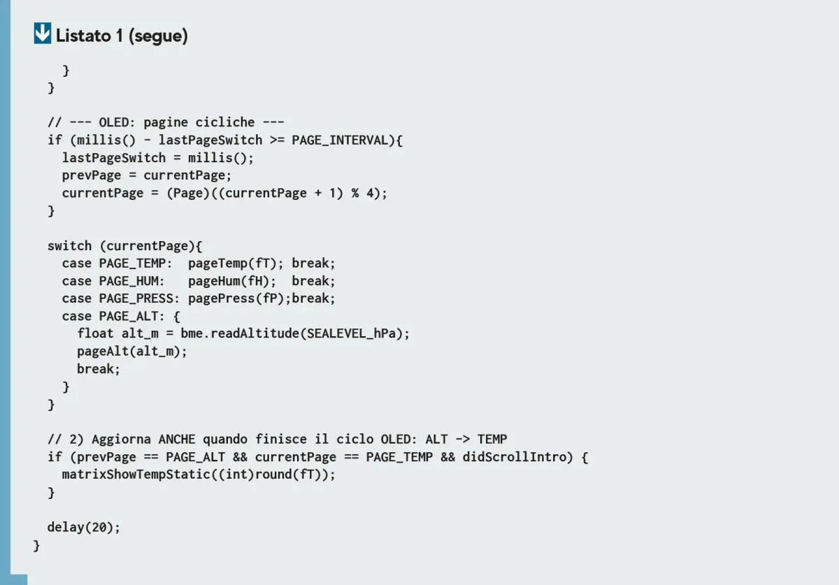
To test the adapter board and the STEMMA Qwiic connection, we wrote for you the simple sketch proposed in Listing 1, which, in association with the breakout board based on BME280 and the OLED display, implements an essential weather station capable of displaying atmospheric pressure and ambient temperature.
To work, the sketch includes the Wire.h, Adafruit Sensor.h, BME280.h, GFX.h, and SSD1306.h libraries, as well as ArduinoGraphics.h and Arduino_LED_Matrix.h to manage the display; in particular, SSD1306.h handles the controller integrated into the OLED display module. In the Setup, the Serial Monitor is initialized for communication at 115200 baud, and then commands are issued to use Wire1, with the instructions:
// Qwiic
Wire1.begin();
Wire1.setClock(100000);
Wire1.setTimeout(1000);
that will be used to make the Arduino UNO R4 communicate with the display and the BPM280 sensor through the Qwiic / STEMMA interface. Once this is done, the I²C-Bus OLED display and the sensor are initialized, then you start acquiring samples of the quantities detected by the latter, sending the result to the display at the corresponding I²C-Bus address. These two operations are repeated in a loop, with a delay time of 20 ms. Note that using the I²C-Bus implies defining the address of the two peripherals in the firmware; in this regard, it should be said that the BME280 breakout typically has address 0x76, which is the default in our sketch; if the query fails and no data appears on the display, it is advisable to change the I²C address in the following line of code:
uint8_t BME_ADDR = 0x76;
replacing 0x76 with 0x77, because breakouts with this preset address also exist. As for the OLED display used in this example, it has an I²C-Bus address of 0x3C, which is fixed and does not vary from manufacturer to manufacturer, because it is defined in the controller chip.
Conclusions
Well, with this we have finished and we leave you to your practical experiments with the Arduino UNO R4 and its Qwiic connection. The application proposed here is one of the many examples of use and employs one board for each I²C-Bus device; however, each one can host, depending on size, multiple breakouts, and remember that the STEMMA/Qwiic connector also supports more than two adapter boards, depending on the current that can be supplied to the bus.