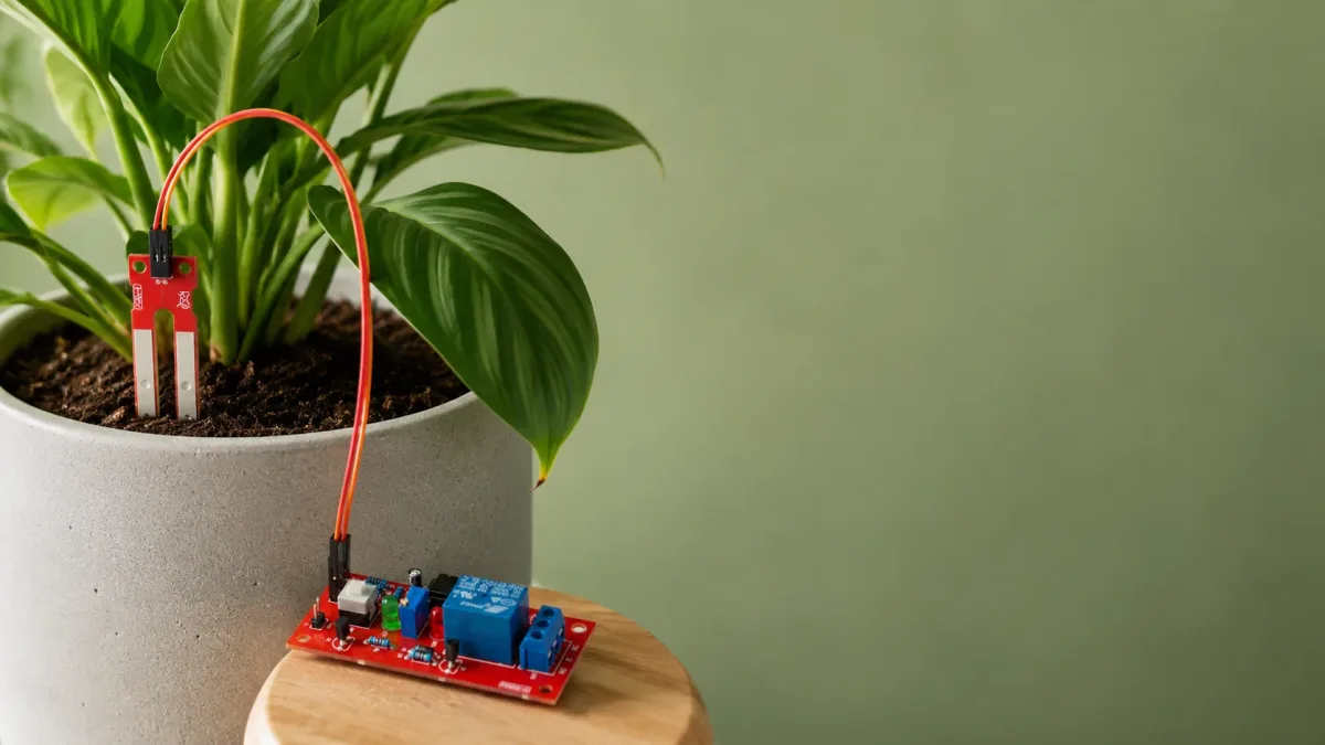
Soil Moisture Sensor
Equipped with a fork-shaped sensing element, it is ideal for detecting soil moisture levels in various applications, not least monitoring plant health, but also detecting the presence of water on the ground.
Measuring soil moisture is useful in many fields, both for crops and, for example, to determine whether there is a risk of water-induced leakage around an electrical installation, where damp soil or a wet floor could be a hazard. In all cases, besides the classic hygrometer, simpler threshold-based devices can be used that provide a visual indication and, if necessary, trigger a local action when the moisture detected by a dedicated sensor falls outside the permitted range. An example is the circuit presented in this article, a kind of humidistat based on a PCB probe and a board housing a comparator and a relay. The actual sensing element is the PCB fork, while the following circuit discriminates the condition detected by the fork. The moisture sensor is a circuit with a relay output and a corresponding LED for visual indication, and through a double switch you can set the assembly so that the relay trips either when a certain moisture threshold is exceeded or when it falls below it. Everything will become clearer with the description of the schematic diagram in the following paragraphs.
Schematic diagram
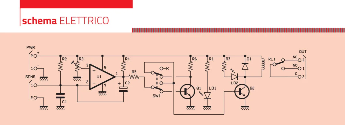
The circuit is based on the LM393 IC, which contains two comparators with open-collector outputs (not by chance, in the schematic you see resistor R4 providing the pull-up on pin 1…), of which we use the one with pin 1 as output and pins 2 (inverting input) and 3 (non-inverting input) as inputs.
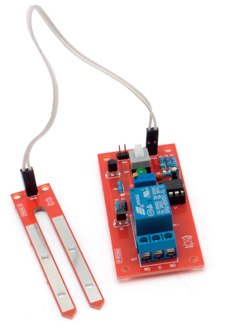
The fork sensor electrically consists of two contacts isolated from each other, which via a two-wire cable connect to contacts 1–2 SENS, so that one goes to ground and the other forms, together with resistor R2, a resistive divider. Indeed, once inserted into the medium whose moisture is to be measured, the two contacts will present an electrical resistance that forms a divider with R2 (terminating on the positive supply line of the circuit) and will determine at the inverting input of comparator U1 a potential difference that is lower the higher the moisture of the medium, whether it be soil, a filter, or something else.
More precisely, the higher the moisture of the soil or other medium between the tips of the “fork,” the lower the resistance between the SENS contacts, and vice versa.
In parallel with the contacts where the fork sensor connects, we placed a capacitor whose function is to filter out any impulsive noise that the connecting wires might pick up and that would otherwise negatively affect the operation of the comparator that follows.
Comparator U1 is connected in a particular way: it is feedback via a capacitor, so the voltage at its output is a ramp that depends on the input voltage at pin 2. The comparator is therefore configured as a threshold integrator, and for the same humidity level and input voltage, depending on the reference potential applied by the trimmer to pin 3, it will present an output voltage that rises over time until it reaches the minimum.
We can analyze the behavior of this portion of the circuit by assuming we start from the power-on instant, that is, from when power is applied, and that all capacitors are discharged, including electrolytic C2: if the voltage across C1 is zero, initially the inverting input pin (2) is at a lower potential than pin 3, assuming the trimmer wiper is in a position other than ground. In this condition the comparator would act as an operational amplifier and would tend toward unity gain at steady state; pin 1 would therefore start at a potential equal to that at the non-inverting input, due to the initial condition of C1 (discharged) bringing the inverting input to zero volts, and of C2 (which in the initial phase is a short circuit), then quickly move to a potential equal to the supply voltage, that is, the maximum positive voltage that the open-collector output stage of the LM393 can present.
Once the charging transient is over (which occurs through both C2 and resistor R2), the voltage across that capacitor equals the output of the divider formed by the fork sensor and R2. Now, if the potential at the inverting input remains below that of the non-inverting input, the comparator output stays high, while if it rises above it, because the detected humidity has decreased (the soil is drier), the condition reverses.
Specifically, the output of U1 tends to assume the low level (approximately ground potential…) and in this condition electrolytic capacitor C2 tends to discharge and then charge with opposite polarity; this initially causes a current flow that lowers the potential at pin 2, but at steady state it charges C2 with positive polarity on that pin and stabilizes the U1 output at the low level.
If humidity rises again and the resistance seen between the SENS contacts becomes such as to bring the inverting input potential back below the reference provided by the trimmer wiper R3, the comparator output tends again toward the high level, so C2 again discharges and then charges with negative polarity toward pin 2 of the LM393.
The operation of U1 can therefore be seen as that of a single-supply integrator, where the output voltage reference can be set with the trimmer to establish the potential toward which the output tends as a function of the resistance presented by the fork sensor.
In other words, drawing an ideal schematic, the integrator input resistance is the equivalent formed by the parallel of R2 and the sensor resistance, while at the non-inverting input the potential is not zero but can be shifted, so as to determine the output state of U1 based on the voltage provided by the sensor itself. Note that at each transition, the comparator output gradually reaches steady state thanks to the capacitive feedback provided by C2. Now let us look at the circuit section that follows the comparator: resistor R5 brings the potential of pin 1 to the lower section of double switch SW1, whose function is to let you decide whether the output relay should activate when humidity exceeds the set threshold or when it falls below it.
Its operation can be explained by analyzing the two positions of the switch.
In the first, the rest position shown in the schematic, the output of U1 biases the base of transistor Q1, which being an NPN goes into saturation when R5 brings it the potential at pin 1 of the LM393, that is, when humidity exceeds the set threshold and consequently the comparator output voltage is high. The other section of SW1 (the one at the top of the schematic) then brings the collector potential (approximately zero) to the base of Q2, which being also an NPN goes into cutoff and leaves the relay at rest. When humidity decreases, for example because the soil of the plant in which the sensor is inserted becomes drier, the comparator output goes to zero, Q1 remains in cutoff and resistor R6 brings its collector high, so the base of Q2 is biased and the collector of this transistor powers the coil of RL1, causing the moving armature to trip and closing the contact between C and NO. In this mode, therefore, the relay trips when there is little humidity, that is, if the soil becomes too dry or if no water is detected on the floor; the contact between C and NO can be used to power a solenoid valve or a soil irrigation pump.
Now let us see what happens when moving the SW1 wiper upward: the output of the LM393 then drives directly (actually through resistor R5) the base of Q2: when humidity is such as to exceed the threshold set by trimmer R3, pin 1 of U1 is at zero volts and the NPN remains at rest; Q1 is irrelevant because it is excluded from the circuit. When the humidity level decreases and the output voltage of U1 rises to the high level, Q2 is biased to saturation and its collector powers the relay coil, causing the moving armature to energize and closing the contact between C and NO.
In this operating mode the relay trips when humidity is excessive, for example due to the presence of water on the ground or because the soil is soaked; the RL1 contact can be used to remove power from a pump if you are controlling an automatic sprinkler or irrigator (in this case powered through C and NC) or to power a pump that sucks water from a flooded room or an alarm indicator.
We end the analysis of the schematic with the power supply, which is applied between the +/- PWR contacts, to which 5V well stabilized must be provided, a necessary condition for the circuit to switch at certain values and for the thresholds to be stable. LED LD1 signals when the device is powered: biased through current-limiting resistor R1, it lights up in the presence of 5V.
A second LED, LD2, is connected with the usual current-limiting resistor (in this case R7) in parallel with the relay coil, to give us a visual indication of when RL1 is energized. In anti-parallel with the relay coil we also placed diode D1, essential to prevent that, due to the inductive nature, when Q2 is cut off it is subjected to a reverse overvoltage spike that would damage its base-collector junction, making it unusable.
Practical implementation
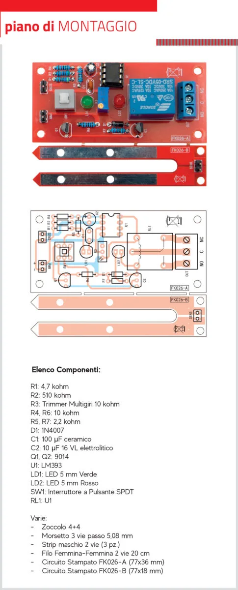
Now that we have reached this point, all that remains is to spend a few paragraphs explaining how to build the device and use it. Let’s start with the printed circuit board — or rather, the boards, because here you need to make two PCBs, even though the drawings in these pages show what is effectively a single assembly plan: there is the board containing the electronics, i.e., the components, and then the sensor “fork” that must be made on a printed circuit board.
Actually, you can also consider using a different two-contact sensor; what matters is that it has two long metal electrodes that can be connected to the SENS points of our circuit. So let’s start with the main PCB, which is double-sided and can be made using the PCBPRODUCTION service with the Gerber files downloadable from the presentation page of this magazine.
Once you receive the board, start placing the components, beginning with the resistors and the silicon diode, then insert and solder the socket for the LM393 (4+4 pins) and the trimmer. Then mount the two transistors, the two LEDs, and the capacitors, the double switch SW1 which is the PCB-mount type, and finish with the miniature relay and the 5 mm pitch three-pole terminal block for the output. To avoid getting the orientation of polarized components wrong (diodes, transistors, and electrolytic capacitor), follow the assembly plan you find in these pages, which is also useful for correctly positioning the IC when you insert it into its socket (when doing so, check that no terminal bends under the body). Once assembly is complete and you have verified its correctness, you can focus on the sensor, which, as mentioned, is intended to be made with a second double-sided board shaped like a two-pronged fork. Once you have the sensor, solder the ends of a small-gauge wire ribbon (0.5 mm² or less is enough) to its two pads, and the opposite ends go soldered into pads 1-2 SENS.
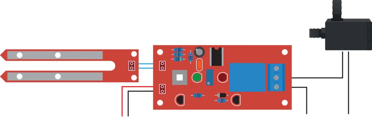
Power the circuit with a stabilized power supply capable of delivering 5 VDC and a current of about 100 mA, respecting the indicated polarity, and if everything has been assembled correctly, you will see LED LD1 light up and, depending on the circuit conditions and the current position of the trimmer cursor, possibly also LD2. Insert the sensor into the soil or place it on the ground if you want to detect the presence of water, then set the double switch SW1 and adjust the trimmer R3 cursor so that, for the desired function (relay activation in the presence of too much or too little moisture), the relay is either active or not. Fig. 1 shows the wiring diagram of the device in the case where you need to control an irrigation pump (SW1 set to the position that connects R5 to Q1) or a water suction pump (SW1 in the position that connects R5 to Q2) that normally must be at rest.
Remember that to detect soil moisture you must push the sensor fork into the ground, while if you want to detect the presence of water on the ground, you must lay the fork flat on the ground, i.e., place it perpendicular until it touches the soil.