RFID with RC522: Radio-Frequency Identification with Arduino
Let’s get to know and learn how to use a board for RF tag identification, easily paired with Arduino.
We have covered radio-frequency identification, better known as RFID, several times before; for example, in issue no. 254 we dedicated an in-depth look at it with a thorough theoretical introduction and some usage examples based on the RFID PN522 module, accompanied by the ever-present Arduino board. In this article, we pick up the discussion again by experimenting with another module, the RFID-RC522, based on the MFRC522 chip produced by NXP (the datasheet is available at the web link https://www.nxp.com/docs/en/data-sheet/MFRC522.pdf).
The RFID-RC522 module
The MFRC522 is a highly integrated RFID reader/writer for contactless communication at 13.56 MHz, supporting the ISO/IEC14443A/MIFARE and NTAG standards.
The transmitter inside the MFRC522 can drive an antenna designed to communicate with cards and transponders without additional active circuits. The internal receiver can efficiently demodulate and decode signals from cards and transponders compatible with the standards listed above.
The MFRC522 supports the MF1xxS20, MF1xxS70, and MF1xxS50 models. It also supports contactless communication with MIFARE transfer rates up to 848 kB (kiloBaud) in bidirectional mode.
The MFRC522 is compatible with all variants of the MIFARE identification protocols MIFARE Mini, MIFARE 1K, MIFARE 4K, MIFARE Ultralight, MIFARE DESFire EV1, and MIFARE Plus RF, grouped under the generic term MIFARE.
Below we summarize the main technical features of the module:
- analog circuit to demodulate and decode responses;
- buffered drivers for connecting an antenna with a reduced number of external components;
- supports ISO/IEC 14443 A/MIFARE and NTAG;
- typical operating distance in read/write mode up to 50 mm depending on antenna size and tuning;
- supports MF1xxS20, MF1xxS70, and MF1xxS50 encryption in read/write mode;
- supports ISO/IEC 14443 with high transfer rate communication up to 848 kbaud;
- supports MFIN/MFOUT;
- additional internal power supply to the smart card IC connected via MFIN/MFOUT;
- supported host interfaces: SPI up to 10 Mbit/s, I²C-Bus up to 400 kBd in Fast mode, up to 3400 kBd in High-speed mode, serial UART RS232 up to 1,228.8 kB/s, with voltage levels depending on the pin supply voltage;
- the FIFO buffer manages sending and receiving at 64 bytes;
- flexible interrupt modes;
- hard reset with low-power function;
- software power-down;
- programmable timer;
- supply voltage from 2.5 to 3.3 V;
- programmable I/O pins.
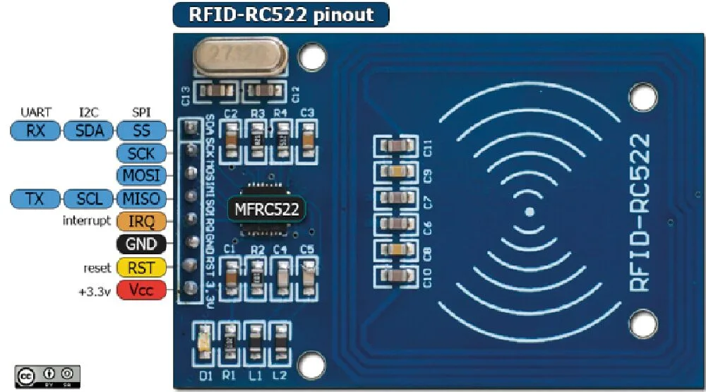
The RFID-RC522 module is detailed in Fig. 1, where you can see all the available connections.
Connecting to Arduino
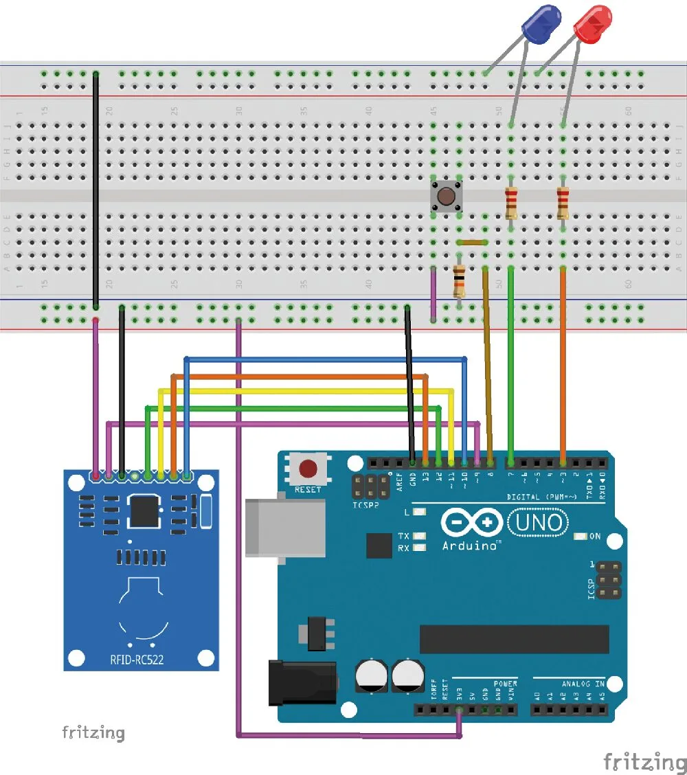
Since all current libraries for using the module with Arduino reuse the SPI connection, we will focus only on that; Fig. 2 illustrates the connection to make for the subsequent tests with Arduino UNO.
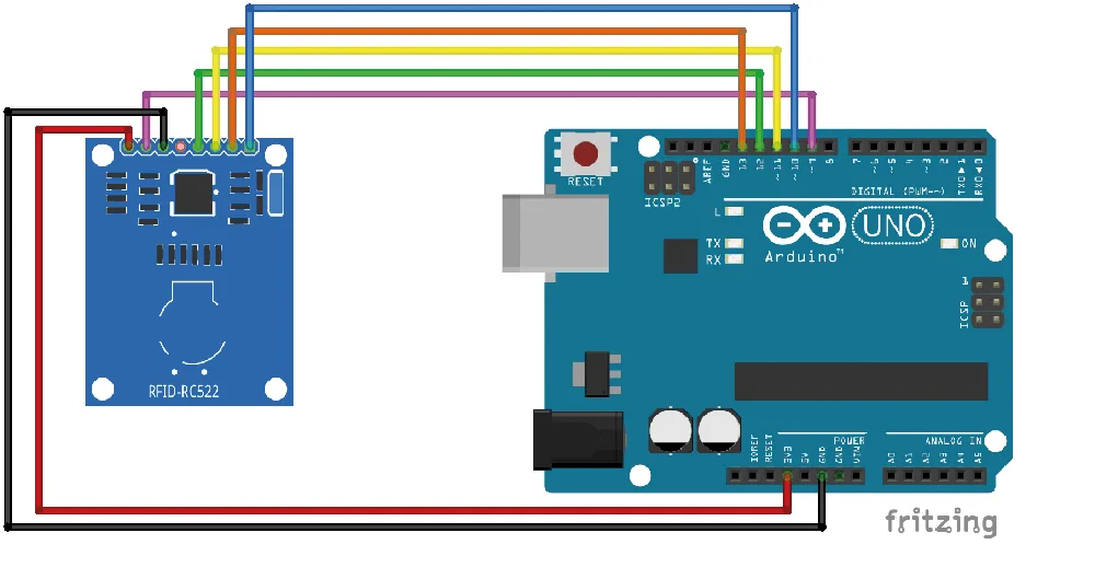
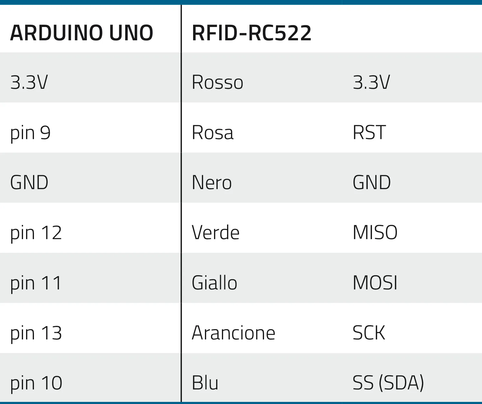
In Table 1 we describe the connections analytically with their signals: on the left are those of the Arduino UNO and on the right the contacts of the RFID-RC522 module with the corresponding wire colors in the diagram in Fig. 2. The IRQ pin of the RFID module should be left unconnected because we do not manage it in this project and do not need it.
Of course, you must be very careful, because swapping just two wires will cause the module to fail; another important thing is power: the module requires 3.3 V, and the corresponding pin on Arduino is right next to the 5 V one; a moment of distraction would almost certainly damage the module.
The board (the RFID module used in the project) comes with two 8-pin strip headers (one straight and one at 90°) to solder as you prefer into the appropriate signal holes, an RFID Tag Card, and an RFID keychain Tag for initial testing.
Libraries for RC522
Using this module is made easier by the availability of specific libraries, of which we have selected two: the one from Velleman and the one written by Miguel Balboa.
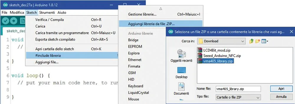
Velleman: it is a minimal library consisting of only two files (RFID.h and RFID.cpp). Once downloaded from the link: https://www.velleman.eu/downloads/29/vma405_library.zip, you need to include it by opening a new sketch with an updated version of the IDE (in our case 1.8.12). Run the command Sketch – Include Library – Add .ZIP Library… and select the .zip file (Fig. 3), then close the IDE; it will be available when you reopen it.
Miguel Balboa: this library, much more powerful and articulated, is recommended by the official Arduino website; it is constantly updated, so it is always best to go to the link https://www.arduino.cc/reference/en/libraries/mfrc522/ or directly to the GitHub https://github.com/miguelbalboa/rfid; at the time of writing, the latest version is 1.4.8.
Its inclusion in the IDE is done in the same way as seen before. This library is quite demanding and requires considerable skills in RFID and programming to exploit it, so we only point it out to more experienced readers, while for the test we will see later we will use the one distributed by Velleman.
Functionality test
Let’s start with a test to verify the connections and the correct installation of the vma405 library. We have prepared a sketch named “RFID_TAG_CODE”; open it in the IDE and upload it to the Arduino UNO, then open the Serial Monitor, which will show the message “Avvicina un Tag al Modulo” (Bring a Tag close to the Module); at this point, bring the Tag close to the part of the module where the radio wave symbols are silkscreened (Fig. 4).
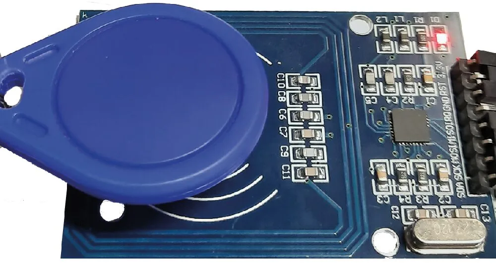
Keep in mind that the module should always be kept away from devices that can generate electric or electromagnetic fields, otherwise it might not work correctly.
The moment the Tag is recognized, the module reads its UID (unique identification code) and displays it on the Serial Monitor, both in decimal and hexadecimal format; in Fig. 5 we can observe the successive reading of two Tags.
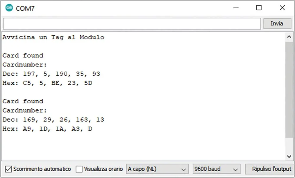
If after the first identification you bring the same Tag close again, nothing will happen because we have not included an alternative action in the sketch; bringing another Tag close instead will give its UID in both formats.
When this test succeeds, you need to decide which Tag will be the “System Administrator” of the circuit we have prepared for experimenting with this module and note the five decimal numbers that make up its UID. For our example, we will use the first group visible in the figure (197, 5, 190, 35, 93).
Access control project
With the help of a breadboard and very few other components, let’s now build a circuit to simulate an access control system using RFID technology with our RC522 module.
The sketch we have prepared can be downloaded and is called Access_Control.rar; it consists of two tabs, and the folder obtained from decompressing the file must be placed in the sketch folder of your IDE; the vma405_library must have been installed beforehand.
The idea is a hypothetical access control system, where the acceptance of a Tag is indicated by the alternating on/off of a blue LED, while rejection is represented by a red LED turning on for about 3 seconds.
Authorized Tags are pre-stored in the EEPROM of the Arduino microcontroller; our sketch supports up to three, but they can be increased up to the availability of the EEPROM. Storage only happens with prior authorization from the “System Administrator,” who has an RFID CARD Tag whose UID must be manually entered in the sketch and which, once read by the module, allows other Tags to be brought close to accredit them and store them in the EEPROM.
From this point on, when you bring an authorized tag near the module, the blue LED will turn on or off with each pass, toggling its state. The red LED, on the other hand, will light up for three seconds when someone tries to gain access with an unregistered tag, effectively denying authorization, and then it will turn off.
Before uploading the sketch to the Arduino, you need to open it and assign the corresponding decimal values of the chosen tag’s UID to the five variables dec_code0 through dec_code4 (Fig. 6), replacing the pre-stored values you will find there.
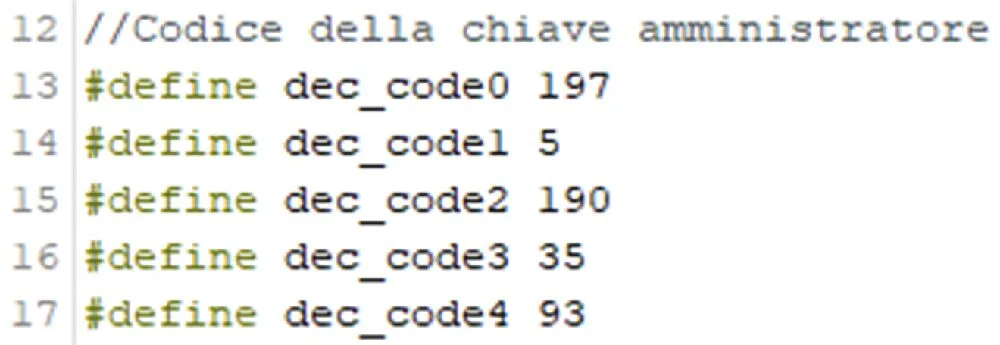
At this point you can upload the sketch to the Arduino and then disconnect the USB cable to remove power. Next, move on to building the practical layout shown in Fig. 7, which explains how to connect all the required components.
Required materials
The materials needed to build the project are:
- RFID-RC522 module
- Arduino UNO
- Breadboard with side power rails (red and black, or red and blue)
- 6×6 mm push button
- Red LED
- Blue LED (or another color of your choice)
- 2 resistors of 220 Ohm
- 1 resistor of 10 kOhm
- 5 M-M jumper wires
- 7 M-F jumper wires
- 1 jumper bridge, 3-pin
- 1 jumper bridge, 5-pin
- 1 jumper bridge, 19-pin
- 4 tags, one of which marked as administrator
Note that regarding jumper wires and bridges, we provided the list to replicate our exact practical layout; of course you can make any variation, as long as you correctly make the proposed connections, otherwise the circuit will not work. Above all, be extremely careful not to reverse the power supply (3.3V and GND), otherwise you risk burning the module!
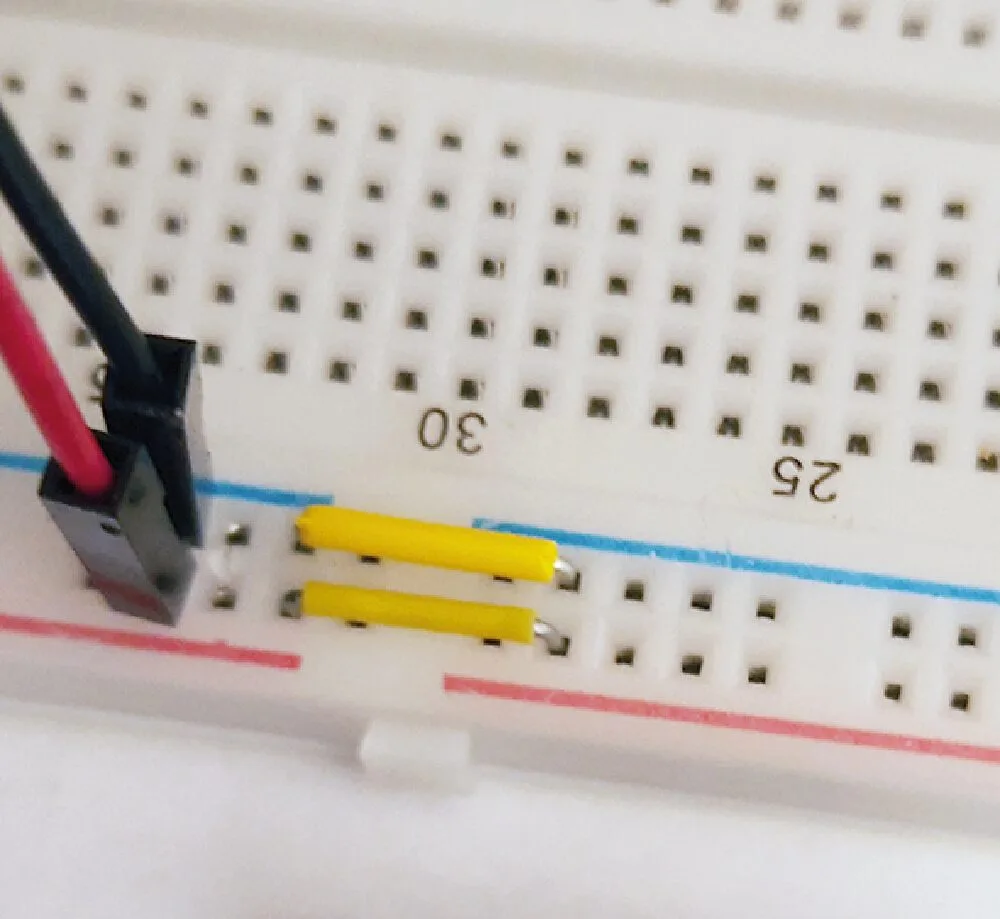
A special note about the breadboard: during our tests we came across a model with the power rails interrupted in the middle section. This was actually clearly indicated by the break in the red and blue silkscreen lines, but since it is unusual, we initially did not notice it. As a result, the RC522 module’s LED still turned on (due to current carried by the signals), but tag reading did not work. We therefore had to add two jumper wires to connect the two rails along their entire length (Fig. 8), i.e., to bridge them.
How the access control works
Once the circuit is complete on the breadboard and the connections are checked, to begin simply reconnect the USB cable from the PC to the Arduino UNO board. You will see the RC522 module’s red LED light up (but as explained earlier, this does not indicate correct power supply), while the two red and blue LEDs on the breadboard remain off.
Now open the Serial Monitor of the Arduino IDE, and the message “Controllo accessi attivo” will appear. The first operation to perform is to bring the Administrator tag near the module. If everything is in order, the two LEDs will blink simultaneously three times and remain on; the Serial Monitor will also show the message visible in Fig. 9, indicating that Administrator mode is active.
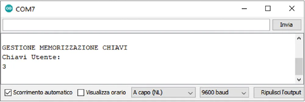
If at first power-up a number other than 0 appears (usually it will be 255), you need to reset the EEPROM. Simply press the push button mounted on the breadboard to achieve the desired result (Fig. 10).
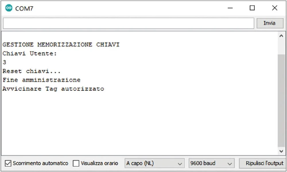
After the reset, you will exit Administrator mode and the LEDs will turn off. You must pass the Administrator tag again to re-enter, then simply bring the tag you want to authorize near the module to store its UID (Fig. 11).
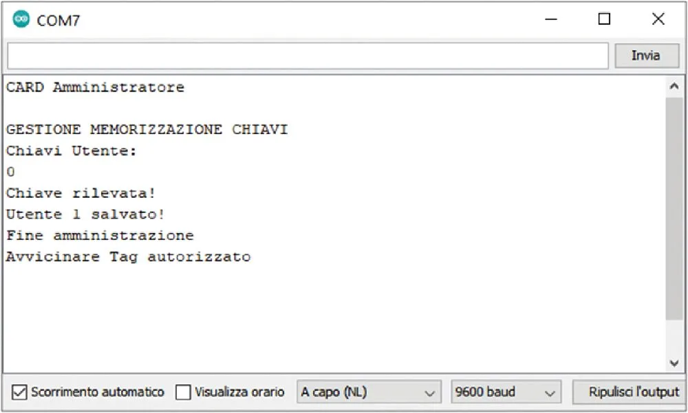
This operation can be performed for a maximum of three tags; after that, no more can be stored unless you modify the sketch accordingly.
Daily use of the system
At this point we can observe the circuit’s behavior depending on the type of tag we bring near the RFID reader; there are two possibilities.
Unregistered tag: the red LED turns on for about three seconds, then turns off; authorization is denied.
Registered tag: if the blue LED is off, it turns on, indicating that authorization has been granted; the LED stays on until you pass the same tag or another registered tag, at which point it turns off.
One last curiosity: if you lack other tags to simulate unauthorized access, you can use your own smartphone. If you have a phone with an NFC chip running Android 5.0 or later, simply enable NFC in the settings and then use the smartphone as if it were a tag.
In fact, when you bring it near the module with the chip side facing it, it will be recognized as a tag, but with a peculiarity that prevents its use as an authorized tag: with each new read, the UID turns out to be different from the previous read. This is easily verifiable with the “RFID_TAG_CODE” sketch. So even if you store the chip as authorized, it will not be recognized on subsequent reads.
In some rare cases, the smartphone may need a specific app to function as a tag. Simply download “NFC Tools” from the Play Store and leave it active, without doing anything else.
Conclusions
We end this article with a suggestion: as you can easily imagine, this project can be expanded by adding, for example, a relay driven by the same pin as the blue LED, which would allow you to activate an actuator such as an electric lock. The only limits are those of your imagination.
Naturally, the greater the complexity of the expansion, the more variations and implementations you will need to make to the sketch, but it will all be a useful programming exercise that will increase your skills and give you great satisfaction.