GSM Emergency Call System with RF Receiver for Elderly and Bedridden Patients
This emergency call system uses a cellular module and an RF receiver tuned to a dedicated transmitter. Pressing the transmitter button sends phone calls and SMS messages to selected numbers, making it ideal for assisting elderly people and bedridden patients.
Changes in society and lifestyle are modifying and sometimes extinguishing customs that are often centuries old, many of which involve the family. While in rural communities and small towns it is still common to find multiple generations under one roof, in large cities families are scattered, and it is frequent to find elderly people living alone, by choice or out of necessity.
It is true that in our highly technological society they are not at all abandoned, since telephones and especially mobile phones exist and can be kept close at hand in case help is needed. However, it is equally certain that something can be improved in the way urgent needs are communicated to the outside world. Indeed, a phone or mobile phone requires dialing a series of keys and reading the display to call neighbors, relatives, medical help, or law enforcement (on smartphones, one must even navigate through icons and menus, which is not so immediate). Having something that can be activated with a simple command in case of need would be ideal.
The emergency call system described in these pages goes exactly in this direction. By simply pressing the button of a very small transmitter worn around the neck with a lanyard or cord (like those used for passes or corporate badges), it activates a GSM module capable of sending calls and SMS with a request for help to a list of pre-programmed phone numbers, almost instantly. The project was born as a life-saving device for elderly, fragile, or bedridden patients and can be customized for other similar uses.
The system consists of a base unit based on a quad-band GSM module (850, 900, 1800, and 1900 MHz), therefore capable of connecting to all available networks, which is a great advantage for a fast connection in an emergency. It also includes a very light mini-transmitter that the person who might need help must carry. The wide coverage of the TX-RX radio system operating at 433 MHz ensures reliable transmission of the alarm request from the mini-transmitter to the base unit, even in large apartments, villas, and even from the garden or from one floor to another.
The system
The mini-transmitter and the rolling-code decoder
With this premise, let us take a look at our emergency call system, analyzing its circuit, with the note that we will describe the base unit but not the portable one, since the latter is an 8110-HCS-TX-1 mini-transmitter sold ready-made and tested. We will only explain that it is based on an HCS300 rolling-code encoder, capable of generating a different code at each transmission, thus ensuring maximum security and exclusivity of the command. The generated code is then used to modulate an AM OOK UHF mini-transmitter tuned to 433 MHz, which radiates the signal into the environment.
The base unit can recognize and anticipate the codes transmitted by the mini-transmitter (or by multiple mini-transmitters) because it implements the HCS300 decoding algorithm. The only condition required for synchronization is the execution of the specific procedure, which starts by pressing the button on the circuit board; we will explain this shortly.
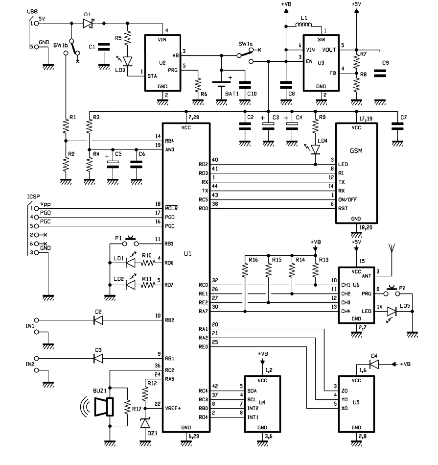
Let us see what it is about by analyzing the electrical schematic of the circuit, whose management is entrusted to a Microchip PIC18F46K20-I/PT microcontroller. The board is modular and, as the schematic shows, lends itself to the creation of multiple applications. In fact, we already used it in issue 223 for the “Save my child” project, albeit equipped with different hardware. Here, the accelerometer is missing (so we do not mount the one labeled U5 in the schematic, nor U4), but we have the hybrid radio receiver and a dedicated button.
The microcontroller is programmed to read the logic state of the output lines of the radio receiver module (Aurel RX-4MHCS hybrid) to detect the arrival of a distress code, the button that starts the self-learning and synchronization procedure for the transmitter to be paired with the base unit, and also to manage the GSM cellular module.
Note that the circuit includes components that can be mounted or not, precisely because we conceived it as an expandable development platform.
The RX-4MHCS hybrid radio receiver
Here, the microcontroller only has to manage the radio receiver, the GSM module, and the external memory. Its task is made easier by the fact that, regarding radio command management, it does not have to handle decoding because U6 is not a simple radio receiver but something more complete, as it integrates decoding.
Indeed, the RX-4MHCS is an AM RF receiver at 433.92 MHz with high sensitivity and selectivity, with integrated HCS decoding, capable of deciphering Microchip’s Keeloq rolling-code algorithm, which provides for transmission strings containing a fixed base code and a 32-bit variable code. This hybrid tunes the signal sent by compatible transmitters (Aurel HCS-TX-1/2/3 OVO, TX1/2/3-HCS-433 HCS, TX-2/4/6 M-HCS, TX-12 CH) and compares the code contained in it with the one or ones stored (in its internal EEPROM, where only the fixed parts of the code of each TX are written) during self-learning. If the transmitted code is among those in memory, the module activates one of its four outputs (CH1, CH2, CH3, CH4) in the mode set via the dedicated pin; otherwise, nothing happens and the module prepares for a new reception.
The outputs are open-collector and four in number because the hybrid can be managed by 1, 2, or 4-channel mini-transmitters. Each channel is active at a low level (transistor in saturation) and at rest at a high level (transistor off).
The security of the rolling-code system
Being a rolling-code decoder, a safeguard system is provided for the case of accidental button presses or out-of-range transmissions. The usefulness is explained by considering that once a transmitter is learned, the decoder synchronizes with its encoder and, by applying the Keeloq algorithm, thanks to an internal counter, knows what code to expect at each transmission. However, if one or more transmissions are lost, the decoder might no longer be able to identify the mini-transmitter, even though it is still learned because its base code has been written into memory.
To limit this possibility, the decoder allows a deviation, meaning it recognizes a transmission as valid provided it falls within the 64 possible combinations that follow the last received one, according to the Keeloq algorithm. If the received code falls within this margin, upon recognition the HCS decoder resynchronizes, i.e., it resets its counter and from that moment restores the “tolerance window” of 64 lost transmissions.
If, on the other hand, this limit is exceeded, the mini-transmitter will no longer be recognized and will need to be learned again.
Operating logic and input management
That said, let us move on to the operation of the whole system, which coincides with that of the microcontroller: after power-on reset, it initializes line RB1 as an input with an internal pull-up to read a normally open contact connected to IN2. Diode D3 protects the microcontroller in case a voltage higher than the PIC supply voltage is erroneously applied to the input. The firmware currently “senses” only IN2, which is used as a simple active-low input, i.e., connected to ground, for example, via switches.
A change in the state of input IN2 triggers the sending of SMS or the execution of phone calls, just like any GSM remote control. It can be used, for example, to detect the opening of a home door or a window, or to alert if a person in a wheelchair falls. In this specific case, a pressure plate can be applied under the seat, like the one from the “Save my child” project, which alerts when the person is no longer present.
IN2 can also be connected to the output of a P.I.R. sensor to detect whether the person is moving, or to a reed switch fitted to the home door; the latter situation is very useful for monitoring people affected by Alzheimer’s disease, who may get lost if they leave home unaccompanied, as well as people with psychological conditions who need supervision by relatives or healthcare staff.
Returning to the microcontroller, we see that another pin initialized as an input is RB3, also equipped with an internal pull-up, which is used to read button P1 (used to force the power-on of the cellular module, which is normally off).
Still during I/O initialization, RB4 is set as an input to read, through the resistive divider R1 and R2, the power-on of the circuit by means of the double switch SW1b; the divider is needed because the microcontroller tolerates a voltage lower than the input voltage present on the power connector. The function of RB4 is reserved for future developments and is explained by considering that the circuit can operate either powered by a mains adapter through the USB port, or by the lithium battery connected to the output of the dedicated charge regulator.
Battery or USB mains power
When SW1 is moved to the “crossed” contacts in the schematic, the rest of the circuit is isolated from the battery, so it is off; if a 5-volt supply is applied to the power input (USB), only the charging stage operates (powered through diode D1, which protects it from reverse polarity). Moving SW1 to the on position, SW1b brings the input voltage to the RB4 line and SW1a powers the microcontroller and everything else with the voltage across the battery (about 4V at full charge…) as well as turning on the switching step-up converter labeled U3, which generates the 5 volts needed by the rest of the circuit.
When the circuit is powered from USB, SW1b brings the input voltage to RB4, which, by implementing its reading in the firmware, allows the microcontroller to detect whether mains power is present; this function is useful for implementing the anti-blackout alarm. Instead, in battery operation, RB4 lets the microcontroller know this and implement possible power-saving strategies (for example, reducing the intervals at which the cellular module is turned on). The RB4 line is the only way the firmware has to know when the circuit is running on battery, because if U1 receives power even when RB4 is at zero volts, it means the circuit is running on battery, while if it is powered, it is running on the voltage taken from USB.
Still on the subject of power, the AN0 line is used to read the voltage level supplied by the lithium battery that powers the microcontroller and the rest of the circuit, except the radio receiver; if the firmware provides for it, it allows the whole system to be put into shutdown when the battery is running low, that is, below a certain voltage threshold.
Outputs, accelerometer and interface to the GSM module
Returning to the I/O initialization, we see that lines RC0, RE1, RE2 and RA7 are initialized as inputs, provided with external pull-ups, and will be used to read the channels of the hybrid receiver (the pull-up is necessary because the module outputs are open-collector). Every time one of these changes state, the microcontroller will order the sending of an SMS or a phone call according to the settings made channel by channel, as will be explained later.
RC3, RC4, RB0 and RD4 are the lines assigned to the accelerometer U4, which, however, is available for future developments since it is not handled by the firmware; the same applies to U5, which would have been managed by RA0, RA1 and RA2.
Line RC2 is initialized as an output and produces a series of digital pulses when the piezoelectric buzzer BUZ1 must produce the acoustic warning note provided by the firmware; two other outputs are RD6 and RD7, which are tasked with turning on LEDs LD1 and LD2.
Interface to the SIM800C GSM module
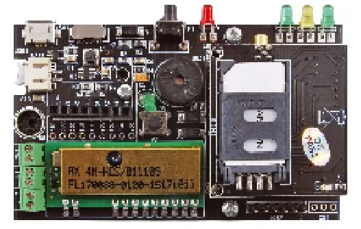
We finish the I/O analysis with RD0, RD2, RD3, RC5, which together with the RX and TX of the UART form the interface to the SIMCom SIM800C cellular module, which in the circuit is mounted on a dedicated adapter board to be inserted into the specific connector provided on the printed circuit board. The compact board containing the SIM800C GSM cellular module has an MMCX 90° antenna connector and connects to the base board via a 2×10-pin male strip with 2 mm pitch, on which power, the power-on control line (PWR), all signals, and the serial communication lines to and from the GSM module are available. The board is supplied already assembled and requires a GSM antenna with an MMCX connector.
The module exchanges data with the microcontroller on transmitted messages (alarms) and received messages (configuration) through the PIC’s UART, which is also used for the cellular module’s setup commands; the remaining lines concern status signals: RD2 reads the output for the “signal” LED which is repeated by LD4, while RD3 reads the Ring Indicator, that is, the cellular contact that provides a high logic level when a phone call is received. Line RD0 allows the module to be reset and RC5 handles power-on and power-off; reset and ON/OFF are implemented by the circuitry on the board on which the SIM800C is mounted.
The battery charger and the step-up converter
Having defined the microcontroller’s I/Os, let’s take a look at the two sections involved in powering the circuit: the battery charger and the DC/DC step-up converter.
The battery charger is based on IC U2, an MCP73831T manufactured by Microchip, which accepts typically 5 volts at its input (the allowed range is between 3.75 and 6 volts), coming, in this circuit, from the USB connector, and provides at its output the current needed to charge lithium-ion or lithium-polymer (Li-Po) cells, delivering up to 550 milliamps. The battery (to be connected to the +/- BAT contacts) can theoretically have unlimited capacity, because at most it will charge in a very long time; however, consider that with a current of 550 mA, a 550 mAh cell charges in one hour; since we have chosen a 500 mAh cell, it will charge in less than an hour.
The IC operates in the typical configuration, where LED LD3 is driven by the STAT output, which goes to a low logic level during charging, while it remains at a high level at the end of charging; it goes to high impedance (open) when the MCP73831T is in shutdown or when no battery is connected to the VB output. VB (pin 3) is the output for the lithium battery. The IC performs constant-current and constant-voltage charging. The charge current (Ireg) is set with the resistor connected to pin 5 (R6, in our case), to whose value it is related by the equation:
Ireg = 1.000/R
where the value of R is in ohms if the current Ireg is expressed in A. For example, with 4.7 kohm you get a limit of 212 mA, while with an R of 2.2 kohm the current is about 454 mA. If pin 5 is left open, the IC goes to rest and draws only 2 µA (shutdown); the pin can therefore be used as an enable.
The 5V boost converter
We finish the description of the schematic with the step-up converter that derives a stabilized 5V from the battery voltage; the stage is based on IC MCP1640BT-I/CHY and is of the inductive-charge boost type. Inside it there is a PWM pulse generator that drives a transistor whose collector periodically closes inductor L1 to ground through the SW pin, charging it and letting it return the stored energy, through pin 5, to filter capacitors C2, C3, C4, C7 and C9 during the pause periods.
The clamp diode that protects the transistor is also internal, which reduces the external components needed to the bare minimum: we have the filter capacitors between Vout and ground, inductor L1, and the resistive divider between Vout and FB that feeds back the PWM generator through the internal error amplifier, stabilizing the output voltage to the desired value. By changing the ratio between R7 and R8, the voltage supplied by the Vout pin can be varied, but that is not our intention.
Component list
- C1, C8, C10: 1 µF ceramic (0805)
- C2, C6, C7, C9: 100 nF ceramic (0805)
- C3, C4: 470 µF 6.3V tantalum (D)
- C5: 4.7 µF 6.3V tantalum (A)
- R1, R2, R4, R13, R14, R15, R16: 10 kohm (0805)
- R3, R12: 1 kohm (0805)
- R5, R9, R10, R11: 470 ohm (0805)
- R6: 3.3 kohm (0805)
- R7: 470 kohm (0805) 1%
- R8: 150 kohm (0805) 1%
- R17: –
- U1: PIC18F46K20-I/PT
- U2: MCP73831T
- U3: MCP1640BT-I/CHY
U6: Aurel RX-4MHCS module
U4, U5: –
P1: 90° microswitch
P2: Microswitch
LD1: 3 mm yellow LED
LD2, LD4, LD5: 3 mm green LEDs
LD3: 3 mm red LED
D1, D2, D3: MBRA140T3G
D4: MMSD4148T1G
DZ1: 2.7 V 500 mW Zener
L1: 4.7 µH 770 mA inductor
BUZ1: Ø 12 mm buzzer without electronics
GSM: GSM module (FT1308M)
SW1: 2-way slide switch
USB1: Micro-USB connector
Miscellaneous:
- 2×10 female connector, 2 mm pitch
- 2-pole terminal block, 2.54 mm (3 pcs.)
- 6-way male pin strip
- 2-way JST connector, 2 mm pitch, with cable
- S1361 PCB (85×51 mm)
Practical construction
PCB assembly
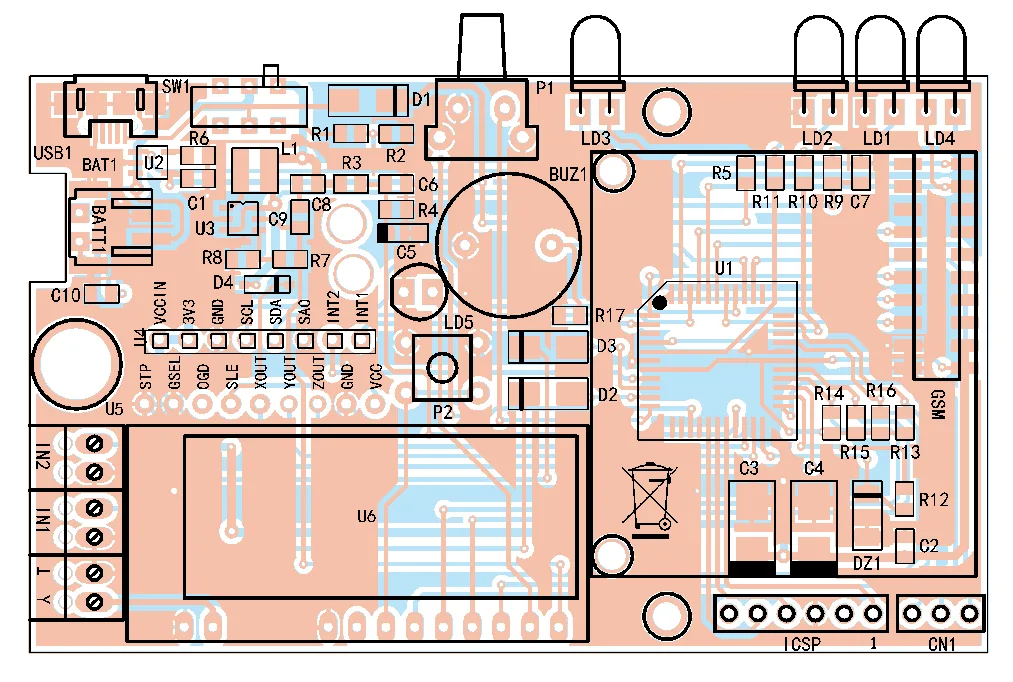
Now that all the blocks of the schematic have been described, let’s see how to build the system starting from the PCB; for the application described here we need the base PCB and the cellular module (which comes with the board already assembled). The base PCB is a double-sided board made by photo-etching, using the copper-side traces downloadable from our website www.elettronicain.it. Once the PCB is ready, place the components starting with the passives and the ICs (the microcontroller and the MCP73831 in SOT-23 package) and finishing with the buzzer, the pushbutton, and the connectors. Apart from the LEDs, the buzzer, the pushbutton, and the terminal blocks, all the other components are surface-mount (including the two-row connector for the cellular module).
Solder the ICs using flux to prevent the solder from accidentally bridging adjacent pins (the pitch is very small) and use a magnifying glass. For a good solder joint, it is advisable to use a 20 or 25 W soldering iron with a fine tip and solder wire with a diameter of 0.5 mm or less; tin the pads first and then cover them with flux to make soldering the terminals easier. It is also a good idea to use a magnifying glass, preferably a table-mounted illuminated one, to check that the components are centered on their pads and that there are no solder whiskers causing short circuits.
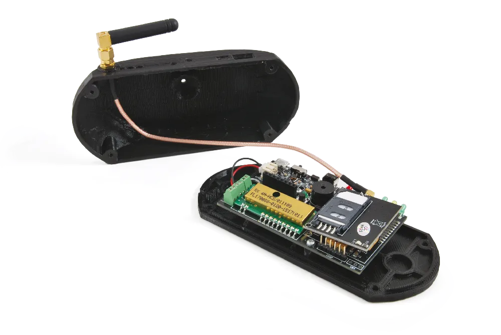
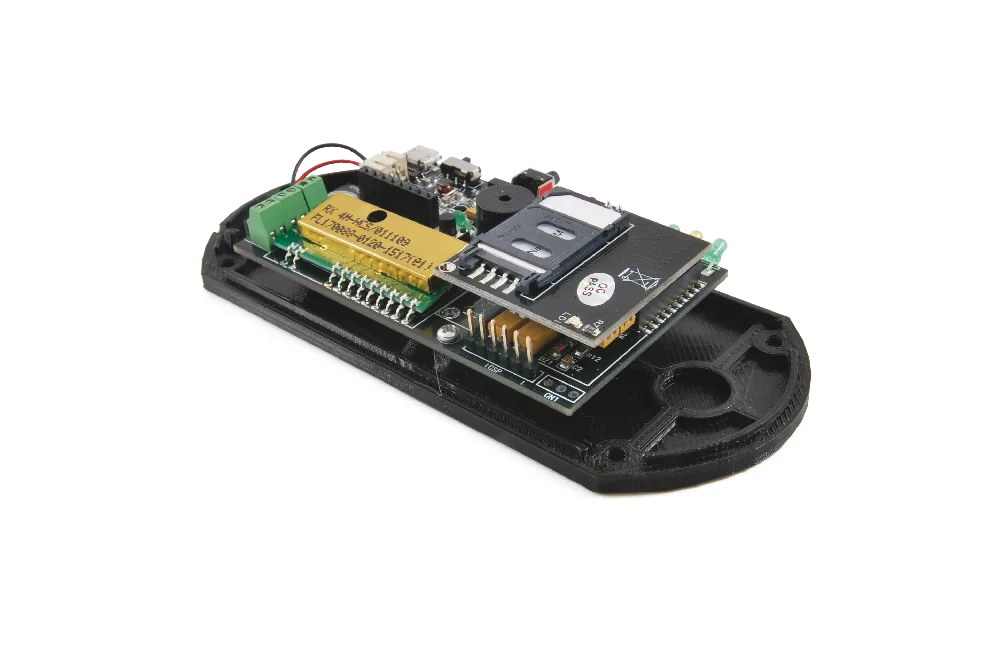
The placement and orientation of polarized components (diodes, electrolytic capacitors, ICs, etc.) can be seen in the assembly drawings and in the photos of the prototype in these pages; note that among the LEDs, the ones on the edge must be bent at a right angle so they protrude from the back of the enclosure (Fig. 1), while only LD5 (used for signaling during the learning phase of the mini transmitters) must be mounted straight and will remain inside the enclosure. As for the radio receiver module, it must be soldered after bending its terminals at a right angle, so that it lies flat, thus reducing the vertical footprint of the board.
The GSM module, the antenna, and the RF receiver
Once the board assembly is complete, insert the GSM module (which you will equip with a suitable antenna with a cable fitted with an MMCX connector) and check that every component is correctly mounted; the circuit must be enclosed in a plastic case, with the antenna routed out. You can extend the connector using a suitable male-to-female cable, fixing the antenna connector to one wall of the case. The photos of the prototype show how we enclosed the board: specifically, we used a plastic case made of an upper and a lower part, 3D-printed with black PLA filament (Fig. 2).
As for the RF receiver, it also needs its own antenna, which can simply be a 17 cm piece of rigid copper wire with insulation, soldered (after stripping enough of the end) to the pad connected to pin 3 of hybrid U6.
Remember that to use the emergency call system, you must insert an active SIM card into the appropriate holder on the board containing the GSM module.
Setup and commands
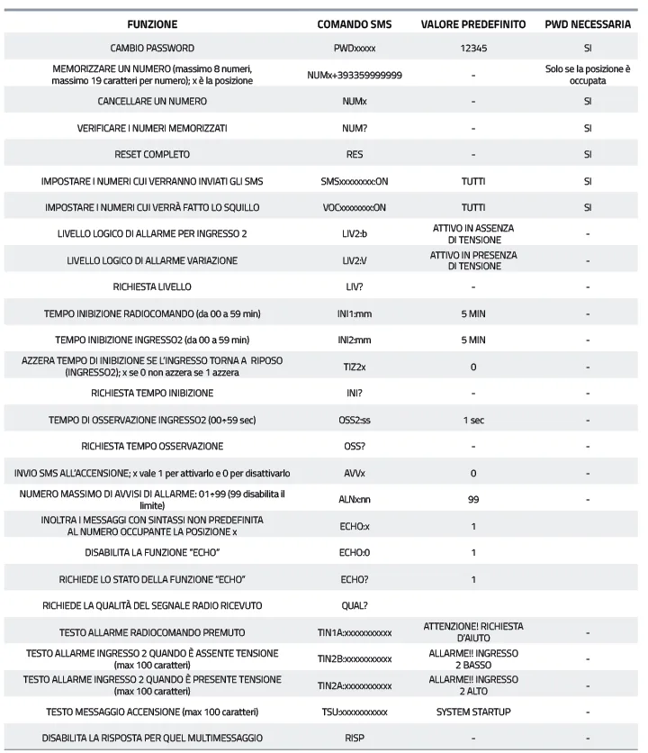
Once installation is complete, you must configure the unit; this is done via SMS. Insert a ready-to-use SIM card without the security PIN into the SIM holder of the 7100-FT1308M module, note its corresponding phone number, and then use a mobile phone to send the required commands, all of which are listed in Table 1.
Configuring the number list
The first things to do are to configure the numbers in the list of those the system will call or send alarm SMS to; to make the procedure easier, since the system is password-protected for this operation, an Easy Setup mode has been provided: in the period immediately after power-on, the system stores the first phone number that calls it and considers it the first number in the list (the waiting period lasts as long as the yellow LED is flashing, and upon receiving the call, LD1 turns off).
This number can make changes even without a password; however, commands can be sent from any phone as long as the SMS includes the password, although to speed up some commands we have provided that those sent from numbers in the list can be issued without a password. For commands to add or remove numbers from the list, the password requirement ensures that only an authorized person can manage the list.
Now let’s look at the commands and their syntax, with the premise that the circuit also accepts SMS containing more than one command; in that case, the commands must be separated from each other by a comma.
SMS command syntax
The first command we examine is the password change, which consists of an SMS of the type PWDxxxxx;pwd, where xxxxx is replaced by the new password (five digits) and pwd indicates the current password. The default password is 12345.
Storing one of the eight numbers authorized to send configuration commands is done by sending an SMS containing the text NUMx+nnnnnnnnnnnnn;pwd, where x is replaced by the position number being stored, n is replaced by the number, and pwd is the current password. Everything must be written without spaces.
Numbers of up to 19 digits are allowed, and the + is what replaces 00 in the international prefix used by mobile phones. For example, to insert the number 00398911512 in the third position, you would use a command like: NUM3+398911512;pwd. The password is only necessary when trying to save a number in a position already occupied by another; instead, if you need to insert a number in an empty position, just send an SMS with the text NUMx+nnnnnnnnnnnnn.
Removing a number is done with an SMS containing the text NUMx;pwd; replace x with the position number where the number to be deleted is located, and pwd is the usual password. For example, to remove the fourth number from the stored list, you need a message containing: NUM4;pwd. To request the list of numbers stored in the circuit, send an SMS with the following text: NUM?;pwd. The board responds to the phone number from which the query originated.
You can check the GSM signal quality at any time by sending the command QUAL?; the system responds with an SMS containing the current status. The message is sent to the phone that issued the command.
Inputs, notifications, and recipients
Now let’s move on to the configuration and status messages for the inputs: LIV? lets you know the status of input IN2, which in this application can only work at voltage level, so it only detects whether it goes low (to ground) or high (for example, when it is open). For this input, you can define an inhibition time using the command INI2:mm (replace mm with the minutes of inhibition); the inhibition is used to avoid continuous alarm notifications if the input, in level mode, remains open.
The same applies to the radio control input, for which both an observation time (i.e., how long the signal must remain at the receiver output to be considered an alarm and trigger SMS and calls) and an inhibition interval are defined, to prevent repeated presses of the transmitter button from starting sequences of calls and SMS.
To define which numbers in the list should receive the calls, send the message VOCxxxxxxxx:ON;pwd, keeping in mind that the same rules apply as for managing the numbers to which notification SMS are directed.
Two separate commands are provided to disable SMS or voice calls: SMSxxxxxxxx:OFF;pwd disables message sending, and VOCxxxxxxxx:OFF;pwd disables phone calls. The x characters represent the positions of the numbers that should not receive help request notifications from the radio remote control or alarm signals detected on the voltage-level input IN2.
Default settings and power-on notification
A clarification is needed regarding the command for setting the numbers to which calls or alarm SMS should be directed: by default in the firmware, and after every total reset, the system directs both calls and SMS to all numbers stored in the list. Consequently, to exclude some of them, you must send the deactivation commands: SMSxxxxxxxx:OFF;pwd or VOCxxxxxxxx:OFF;pwd, specifying the positions to exclude. This is only necessary if you want to exclude numbers; otherwise, no action is required.
The system sends an SMS to the phone number occupying the first position in the list every time it receives power. This function can be disabled/enabled with the commands AVV0 (disable) and AVV1 (enable); the default text is SYSTEM STARTUP.
Customizing messages and reset
Now let’s look at the commands that allow you to store or overwrite the text of the SMS to be sent: the syntax is TINn:xxxxxxxxx, where n must be 1 for the radio remote control and 2 for the alarm due to input 2, while the x characters correspond to the message text, which must not exceed 100 characters in length.
An essential setting is the observation time for IN1, which is done with the command OSS1:ss, where ss is replaced by the time (between 0 and 59 seconds): it tells the circuit how long the mini transmitter button must remain pressed to avoid generating false alarms due to accidental presses or interference signals that could pass through the connections.
You can also define an observation time for IN2, in the same way, by issuing the command OSS2:ss; in this case too, the time serves to avoid false alarms if you connect the input to contacts for doors or PIR sensors.
You can also request the currently set times via SMS (command OSS?).
We close the overview of commands with the one that restores the default settings: it is RES;pwd. The response message to this command via SMS is “Reset eseguito”.
The rest of the commands are described in Table 1, to which we refer for further details.

Learning transmitters
Now let’s move on to the radio remote control section: to ensure reception of the signal transmitted by the portable mini transmitter that the person to be protected will wear, you will need to store the transmission code of the corresponding transmitter in the RX 4MHCS module.
To perform this operation, bring the transmitter close to the receiver, but not attached to the module: keep it at a distance of half a meter. Remember that only transmitters with the Manufacturer Code Futura Elettronica can be learned, since Keeloq encoders and decoders have a fixed part of the code that is unique for each manufacturer; purchasing TX and RX 4MHCS module from Futura Elettronica solves the problem already.
The self-learning procedure starts by pressing and releasing the programming button P2; entering the learning phase is signaled by the LD5 LED blinking rapidly for 10 seconds: during this time, operating near the RX 4MHCS, pressing any key on the transmitter will be learned by the receiver. Successful programming of the RX 4M-HCS is indicated by the LED with a steady light, after which it turns off. In this case, all available buttons on the transmitter have been coded, and pressing each one will activate its corresponding output. If you use a single-channel transmitter, which is the most advisable option, only that one is learned, but note that the learning, concerning the transmitted code, is valid even if the TX is multi-channel and does not need to be repeated for each channel.
The procedure just described must be repeated if you wish to pair more than one transmitter with the unit, so for each additional TX you repeat it exactly the same way.
The self-learning of a one, two, three, or four-channel transmitter can be performed indifferently by pressing any key, since the microcontroller handles the standard bit sequence for assigning each individual channel.
Output modes: bistable or monostable
Note that although the outputs can operate in bistable or pulse mode, after self-learning the monostable type is set by default; this is not a problem at all, because the microcontroller prefers it, since the firmware detects the transition of the logic level on any of the four outputs. If you set bistable mode, in case of activation of the mini transmitter, the microcontroller would receive an alarm signal every two presses of the button, and this could limit the ability of the person in difficulty to ask for help.
Clearing the code memory
We complete the description of the learning process with the procedure for clearing the code memory: to clear the memory of the RX 4MHCS, press and release button P2, and when the green LED LD5 starts blinking, press the button again and hold it for about 5 seconds, and in any case until the LED stops blinking, at which point release P2. Five sequential blinks of the LED will indicate that the memory has been cleared, after which no transmitter with HCS encoding will be recognized (because the clearing is not possible selectively but only for all learned codes) and the outputs will be set to pulse mode.
Conclusions
This project, like Save my child, allows you to easily create a remote alert system (teleassistance, if you prefer) capable of protecting the health and safety of the most vulnerable people, through an effective and widespread means of communication such as cellular telephony. The availability of optional peripherals on board allows you to expand the possibilities of use and customize the system to adapt it to particular conditions, simply by adding an accelerometer, etc., and adjusting the firmware.