
Pedometer Breakout Board with STM201M
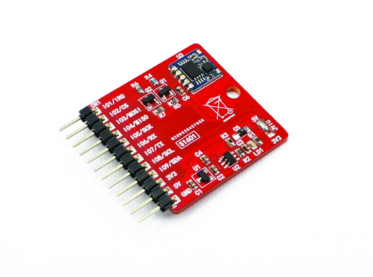
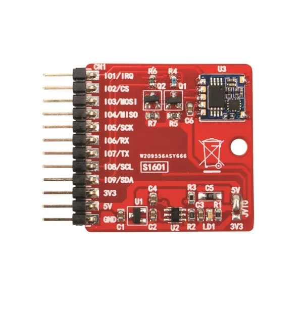
SKU 7100-FT1601MEAN 8219671099233Item type: AssembledBreakout boards
Description
|
Pedometer based on the very small accelerometer module marked STM201M, mounted on a breakout board. Interfaced via I²C-Bus to an Arduino board, it detects and counts steps during the day, physical activity or work. The module is a 3D pedometer with a functional IC chipset that includes an acceleration sensor (G-sensor) and an MCU to interface and control it. With the 3D MEMS sensor (G-sensor) and the high precision of the 3D pedometer algorithm, it can provide accurate step counting in any direction. This chipset has excellent features, a compact size and low power consumption. Thanks to the standard I²C digital interface, it can easily be integrated into various types of pedometer function systems or used with the Arduino development platform. A demo application is provided to test the breakout board’s features, along with the libraries for managing the breakout board. Warning! The Arduino UNO rev.3 board is not included. |
| Circuit diagram |
|
|
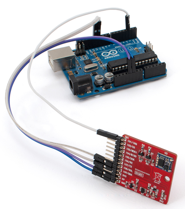
| Example of the breakout board connected to the Arduino UNO board |
 |
| The STM201M pedometer module |
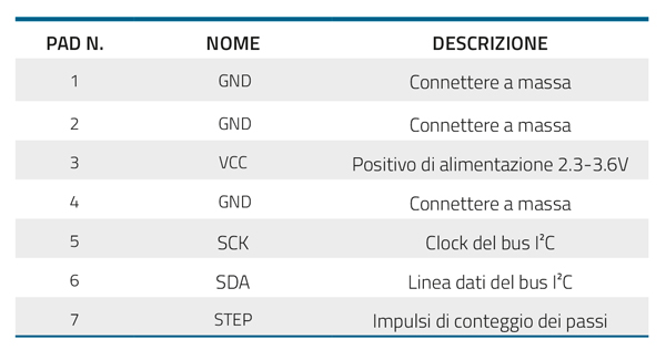
| The STM201M module is a 3D pedometer with a functional IC chipset that includes an acceleration sensor (G-sensor) and an MCU to interface and control it. It is manufactured by the Chinese company NiceRF and uses the standard I²C interface; with the 3D MEMS sensor (G-sensor) and the high precision of the 3D pedometer algorithm, it can provide accurate step counting in any direction. This chipset has excellent features, a compact size, low power consumption (draw of 5 microamps in sleep mode and 60 microamps in normal operation…) and so on. The standard I²C digital interface (in which our module acts as a Slave) ensures that it can easily be integrated into various types of pedometer function systems, and for our idea of pairing the breakout board with Arduino, it is the optimal solution. The module can provide step information in two ways:
|
 |
| Breakout Boards |
|
Breakout boards are prototyping boards containing the component in question already soldered on, with its connections brought out to the edge of the board on easily usable pins with a standard pitch and termination; the pads are generally spaced at a 2.54 mm pitch, like those of classic DIP ICs. To help those who would like to use SMD components but lack the means or skill to solder them, a number of ICs have been selected (including sensors, switching power supplies, battery chargers, linear amplifiers, etc.) and mounted on ready-to-use boards. These breakout boards are an aid both for those who want the best of SMD electronics already available in a “traditional” format, and for those who -while able to work with SMD components- need to have such components available on prototyping boards to apply them to existing circuits and run tests, or to build prototypes that integrate the functions of the relevant ICs before creating the final PCB of a device. |
| Documentation and useful links |

Technical details
| Power supply | 5 Vdc / 3.3 Vdc |
|---|---|
| Resolution | 1 step |
| Communication level | 5 Vdc / 3.3 Vdc (selectable via jumper) |
| Communication | I2C |
| Dimensions | 33x33 mm |
| Operating temperature | from -10°C to +50°C |
Related products
-
 Breakout boards
 -
 Components & enclosures