
RGB LED Matrix Controller
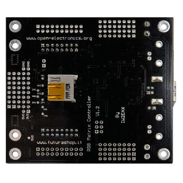
SKU 7100-FT1286MEAN 8219671078788Item type: AssembledDisplays, Mood lighting & gadgets
Description
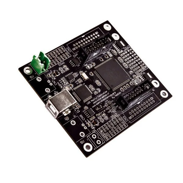
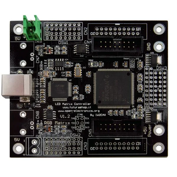
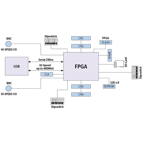
LED Matrix is a very powerful FPGA-based development board, ideal for educational experiments as well as professional projects. It features a Xilinx Spartan 6 FPGA (XC6SL9) with 102 I/O, 11,000 flip-flops, and 32 BlockRAMs. Of the 102 I/O, 62 are available for general use, while the rest are assigned to dedicated functions such as USB serial, EEPROM memory, SD card, boot flash, etc.
The FTDI FT2232HL chip manages the serial interface and provides, from a single USB 2.0 connection, two virtual serial ports that at the hardware level are actually one high-speed serial and one 8-bit parallel. This allows one serial port to be used for loading firmware and the other for data acquisition.
This board can indeed be programmed directly via USB thanks to the preloaded bootloader. Therefore, for both use and program upload, the Xilinx JTAG cable is NOT required, resulting in significant cost savings and simplified board management. Bitstreams (FPGA programs) are loaded via a freely available terminal software.
The board can manage up to 15 different bitstreams, whose startup can be selected from the bootloader menu directly from the terminal.
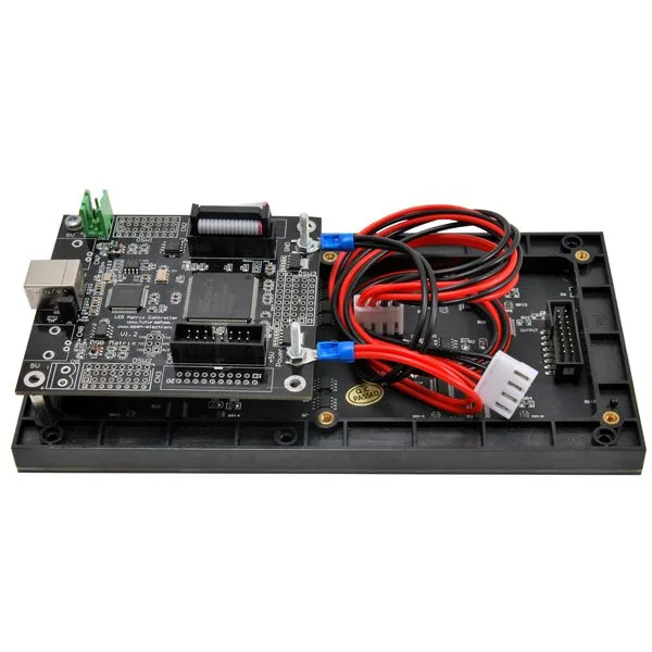
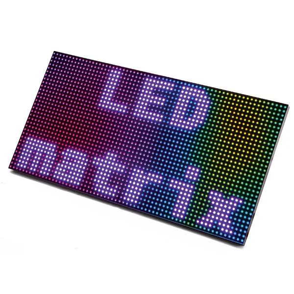
To test the board immediately, in addition to the bootloader, LED Matrix is supplied with an application for managing graphic panels with RGB LED dot-matrix displays (max. 4 panels 32×32). Thanks to the FPGA and its parallel processing capability (multi-thread), LED Matrix can handle even very fast animations and execute programs at extremely high speed. Display management via PC is done through the free software Jinx.
The board can be powered via USB or via an external 5 V supply; board current draw: 100 mA; dimensions (mm): 89×79.
SD management (for standalone use) and cascade connection (to extend the display) can be enabled by activating the corresponding modules, available as optional packages (see related products).
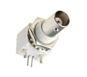
Note: RGB LED graphic panels and the power supply are not included (see related products). BNC connectors are present on the board starting from January 1, 2019.
Block Diagram of the LED Matrix Board
The FPGA
It is a very versatile and atypical device because it can perform the tasks of microcontrollers and microprocessors, without being either one or the other, and it can adapt to various tasks thanks to the great flexibility offered by an architecture that is not rigid like that of a microcontroller but consists of a large number of elementary logic devices (logic gates, flip-flops and counters, multiplexers/demultiplexers, encoders and decoders…) and an ALU, all connectable to each other via internal CMOS switches in various ways to achieve an infinite number of configurations. The interconnections are electrically “programmable” so as to connect the logic devices to each other to obtain the desired logic function; they also allow the internal logic to interface with the I/O pins.
The processing capacity of an FPGA is defined by the number of “equivalent gates,” i.e., logic gates corresponding to all integrated devices (we know that in general logic devices can be composed with the basic gates NOT, OR, NOR, AND, NAND, XOR). The simplest FPGAs have about 10,000 gates, while the most powerful ones reach 2 million gates (corresponding to about 500,000 CD4001-type chips).
Another parameter to evaluate when choosing an FPGA is the number of Input/Output pins, which in the smallest models is about 50, while in the largest (in BGA packages) it reaches 1,000. The ratio between available I/O and equivalent gates is another crucial factor: devices with few I/O and many logic gates can perform many calculations but are suitable for applications where there are few elements to interface with, while FPGAs with many I/O are suitable for managing processes where many signals need to be acquired and sent, i.e., for parallel processing.
The arithmetic logic unit (ALU) contained in FPGAs is very fast and has clocks from 200 MHz upward. Compared to the use of classic microcontrollers and microprocessors, the FPGA offers advantages in the ability to reconfigure logic at any time, in hardware versatility, and in the possibility of implementing even very complex circuits. To define the logic to program into the FPGA chip, a program is needed that “translates” the circuit schematic into a binary programming file, which is then transferred to the FPGA’s boot memory via a dedicated programmer (in the case of the Spartan 6, this is the JTAG).
Documentation and Useful Links
Technical details
| board current draw | 100 mA |
|---|---|
| dimensions (mm) | 89x79 |
You may also like…
-
 BNC
BNC
Related products
-
 Displays
 -
 Displays
 -
 Displays
 -
 Pin headers
 -
 Displays
 -
 Displays
 -
 Displays
 -
 Displays