
MCP23017 I/O Expansion Breakout Board
SKU 7100-FT1650KEAN 8219671099233Item type: KitBreakout boards
Description
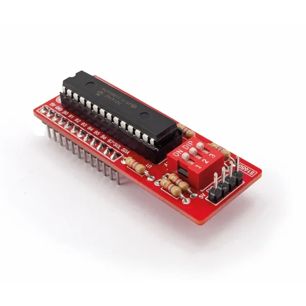
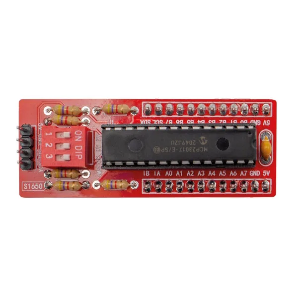
| Breakout board based on the Microchip MCP23017 I/O expander, which can be driven by a microcontroller (Arduino, for example) via the I²C-Bus serial interface, providing 16-bit I/O expansion in serial or parallel mode. Each GPIO can be an output capable of sourcing up to 25 mA, or an input with an optional internal pull-up resistor. The breakout also features two IRQ (Interrupt Request) pins that can be configured on the inputs whose changes need to be monitored. On the board, all the I/O pins, the serial communication pins and the power pins are brought out to 2.54 mm male header strips positioned along the sides of the module, making it easy to mount on a breadboard or other boards. A 4-pole strip is also provided on one of the short sides of the module for connecting to the bus. The ability to set eight addresses for the unit via DIP switch allows up to eight I/O expanders to be placed on the same bus, controlling a maximum of 128 I/O lines. The board’s supply voltage is 5 Vdc. |
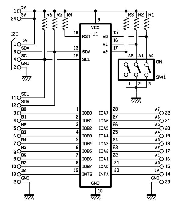
| Circuit diagram |
|
|
| The Microchip MCP23017 IC |
| The MCP23017 is a 16-bit I/O expander with two 8-bit ports, using the I²C bus to communicate with the master system. With just two wires, it allows the state of 16 lines to be read or set. It consists of several registers for configuring the I/O as inputs or outputs, managing polarity and storing data. It also has two interrupt pins, which can be associated with the ports individually or combined with a logical OR for both. It can be set to 8 different addresses, allowing up to 128 I/O lines to be managed using up to 8 I/O expanders on the same bus. |
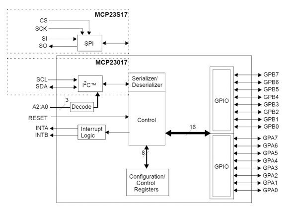 |
| Block diagram of the MCP23x17
The main features of the MCP23017 are: |
| Breakout boards |
|
Breakout boards are prototyping boards with the relevant component already soldered on, whose connections are brought out to easy-to-use pads with a standard pitch and termination; these connections are typically 2.54 mm pitch pads, like those of classic DIP ICs. |
| Example of the breakout board connected to an Arduino UNO and an 8-relay module |
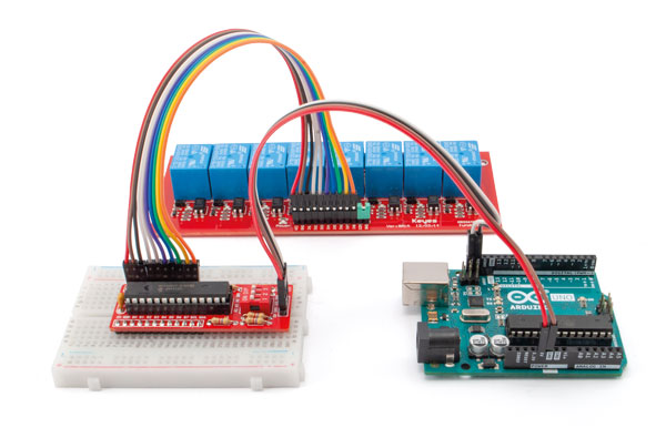 |
| Warning! The Arduino UNO rev.3 board, the breadboard and the relay board are not included. |
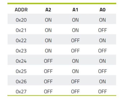
| Setting the MCP23017 device address |
 |
| Documentation and useful links |
Related products
-
 Components & enclosures
 -
 Breakout boards