
High Side Driver for the Mercury System
SKU 7305-SB140EAN 8219671102865Item type: Assembled, Shields & add-onsIoT (Internet of Things)
Description
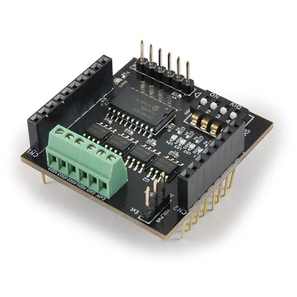
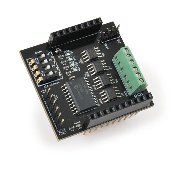
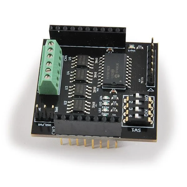
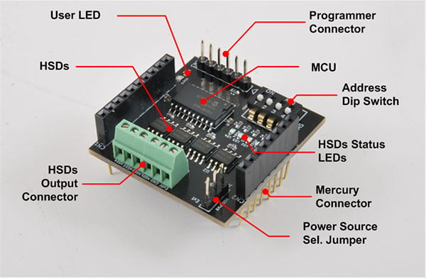
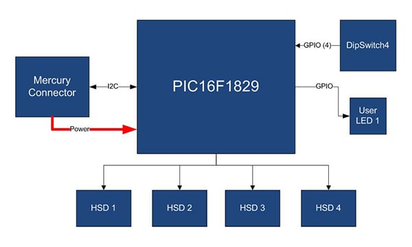
| 4 channel HSD (High Side Driver) board, able to control a load of up to 1 A per channel. The board connects to the Base Board (BB) of the Mercury system over the I2C bus. Its address can be set dynamically with the 4 way dip switch, which gives up to 15 different addresses (address 0x00 is reserved for the I2C bus). The board has a jumper for selecting the power source: internal (VBat) or external through the dedicated terminal. The heart of the system is an 8 bit RISC PIC16F1829 microcontroller made by Microchip Technology Inc. | |||||||||||||
| Hardware | |||||||||||||
 |
|||||||||||||
|
|||||||||||||
| Microcontroller specifications | |||||||||||||
|
|||||||||||||
| Hardware diagram | |||||||||||||
 |
|||||||||||||
| Mercury System | |||||||||||||
| Mercury System (MS for short) is a modular system for developing connectivity and IoT applications. It uses several kinds of boards (logic unit, modem, slave board with sensors and actuators, power boards and so on) and a complete SW framework for building complex applications. Scalability, ease of use and modularity are the key factors, and they come from using a mixed set of components that let the system be assembled like a model made with LEGO© bricks.
The set of boards that makes up the Mercury System is organised into the following “families”: • Base Board (BB): It is the “brain” of the whole Mercury System and holds the main logic unit, several communication buses and the connectors for interfacing the slaves. It also has a simple power supply and a charger for a single LiPo cell (enough for the power needs of simpler systems). It comes in different variants, depending on the microcontroller unit used. • Modem Board (MB): this is the board that provides network connectivity. It comes in different variants, depending on the network interface (GSM / GPRS, Wi-Fi, BT, Radio and so on). It is interfaced to the base board over a dedicated serial line. • Power Board (PB): this is the board that meets the particular power needs of the system, where required. They vary according to the power need to be met (high power, solar harvesting, piezoelectric harvesting and so on). • Slave Board (SB): these are the peripherals of the system and they vary with the specific sensor or actuator fitted. Typical examples are SBs with relays, temperature sensors, RGB LED controllers, servo controllers, accelerometers and so on. They talk to the BB over I2C or UART with a dedicated command set. • Expansion Board (EB): these are the boards that allow Mercury boards to be connected side by side. Some variants can carry a display, a battery holder and so on. • Brain-Less Board (BL): these are the boards with no controller. In general they carry very simple sensors or actuators that do not need the bus interface. They are an alternative to slave boards for applications that have to keep costs down. Slave Boards and Modem Boards come pre-programmed with firmware implementing a dedicated command set for high level control, while Base Boards carry a software framework that provides all the low level services (operating system, peripheral drivers, system services and so on), leaving the user only the application level logic to develop. |
|||||||||||||
 |
|||||||||||||
| Mercury System Framework | |||||||||||||
| Mercury System Framework (MSF) is a layered software framework designed specifically to support application development with the Mercury System. It gives the user a complete set of basic functions for easily interfacing the Slave Boards (SB) and the Modem Boards (MB), as well as a number of software and infrastructure system services. | |||||||||||||
 |
|||||||||||||
| The framework is made up of the following components:
HAL (Hardware Abstraction Layer): the purpose of this layer is to abstract the hardware dependencies away from the upper layers.
OSL (Operative System Layer): this layer is a lightweight RTOS providing basic services to the system, such as scheduling tables for the various tasks, events, SW timers, alarms and so on. |
|||||||||||||
 |
|||||||||||||
| The Slave Boards of the Mercury System | |||||||||||||
| The layout of the Mercury Slave boards is standardised, to simplify interfacing with the Base Board and to guarantee a high level of modularity and scalability. Every slave board has an I2C (Inter Integrated Circuit) communication line and a four position dip-switch for setting the bus address of the slave board dynamically. Addresses 0x01 to 0x0F are available for the Slaves, while address 0x00 is reserved for broadcast communications. In this way up to 15 devices can be connected to the Base Board using the dynamic addressing scheme. That number can be raised further by reprogramming the Slave with an address supplied by software. In addition, two open collector digital lines connected to the external interrupts of the base board are provided for slave boards that have to raise asynchronous interrupts. Slave boards that need higher bandwidth and peer-to-peer communication can also be interfaced using a further UART channel.
There are several sub-families of Slave Board:
The table below gives some examples for each sub-family:
|
|||||||||||||
| Documentation and useful links | |||||||||||||
Technical details
| Board type | Slave Board (SB) |
|---|---|
| Addressing | 4 Dip Switch |
| Peripheral | 4 HSD channels – ST VN7040A |
| HSDs | the board is fitted with 4 ST HSD drivers, model VN7040A |
| HSD Output Connector | 4 HSD channels, GND and the external power connector |
| MCU | PIC16F1829 main controller board |
| Programmer Connector | Microchip PicKit 3 programmer/debugger connector |
| Memory type | Flash |
| Memory | 14 KB |
| CPU Speed (MIPS) | 8 |
| RAM Bytes | 1,024 |
| Data EEPROM (bytes) | 256 |
| Digital Communication Peripherals | 1-UART, 1-A/E/USART, 1-SPI, 1-I2C1-MSSP(SPI/I2C) |
| Capture/Compare/PWM Peripherals | 2 CCP, 2 ECCP |
You may also like…
-
 IoT (Internet of Things)
 -
 IoT (Internet of Things)
 -
 IoT (Internet of Things)
 -
 IoT (Internet of Things)
 -
 IoT (Internet of Things)
 -
 IoT (Internet of Things)
 -
 IoT (Internet of Things)
 -
 IoT (Internet of Things)
 -
 IoT (Internet of Things)
 -
 IoT (Internet of Things)
Related products
-
 Wi-Fi modules
 -
 Wi-Fi modules
 -
 ESP8266 / ESP32
 -
 ESP8266 / ESP32
Espresso Lite V2.0: the WiFi development board for IoT devices
€13.52excl. VAT€16.50incl. VAT -
 ESP8266 / ESP32
 -
 IoT (Internet of Things)
Trace&Follow – WiFi-Ethernet Energy Monitoring and Machine Control
€350.00excl. VAT€427.00incl. VAT -
 ESP8266 / ESP32
 -
 ESP8266 / ESP32