
Earthquake Sensor Breakout Board – Omron D7S
SKU 7100-BREAKOUT019EAN 8219671092586Item type: AssembledSensors, Sensors
Description
|
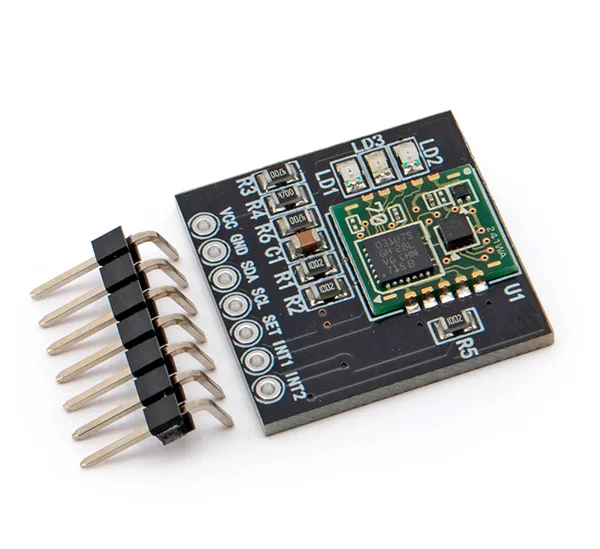
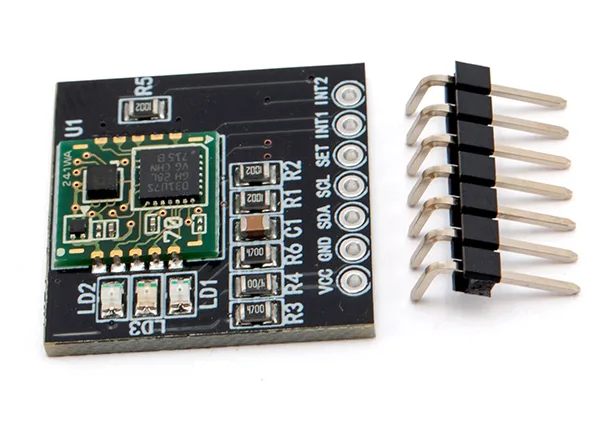
Breakout board built around the Omron D7S, the smallest seismic sensor in the world. The D7S contains a three-axis accelerometer, of which only two axes are used while an earthquake is being detected; they can be selected by the user or automatically, according to how the sensor is tilted. Warning: the pin header has to be soldered. Click here to read the full article published in Elettronica In no. 224 – April 2018 |
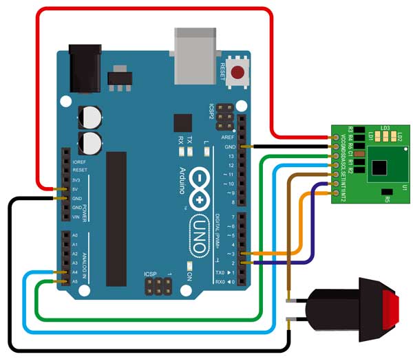
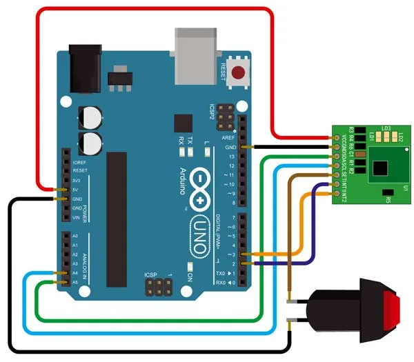
Wiring diagram of the D7S sensor with an Arduino UNO. |
| The D7S sensor |
| One of its most important features is the warning it gives, through the INT1 pin, of seismic events that could have catastrophic effects on electronic equipment; this makes it possible, for example, to switch equipment off before the vibrations caused by the earthquake can actually cause that damage. Protecting the equipment is essential if, after a seismic event, working apparatus is still to be available to prevent further damage. The signal available from the INT1 contact can also be used to trigger alarms and, why not, to activate mechanical protection for measuring instruments and for the rooms that house them. The sensor issues two signals: shutoff and ground collapse. The first occurs if the earthquake is judged to be of intensity 5 or above on the JMA (Japan Meteorological Agency) intensity scale and meets the conditions laid down by JEWA (Japan Electrolyzed Water Association standard JWA) in standard JWDS 0007, appendix 2, while the second occurs if the ground tilts by roughly 20°. |
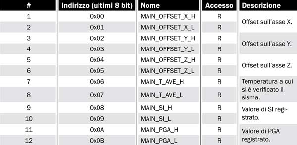
Summary of the register block that holds the earthquake information. |
| The sensor also has an internal memory holding the data for the last five earthquakes recorded and for the five largest ones, plus of course all the configuration settings. The D7S contains a three-axis accelerometer, of which only two axes are used while an earthquake is being detected; they can be selected by the user or automatically, according to how the sensor is tilted. The presence of an I²C bus lets any microcontroller fitted with it, Arduino included, change the sensor settings or read the earthquake data. The D7S sensor has three function pins in all: two of them (INT1 and INT2) are signalling pins and the third (SET) is a line used to change the operating state. Before using the sensor the initial installation procedure has to be carried out: the sensor must measure the offsets of the selected axes and store their value in the internal memory; these offsets are then used to identify the collapse condition, by comparing them with the current ones when the seismic event is detected. After the initial installation stage the sensor goes into standby until an earthquake starts, when it begins computing the data for the event; it stays in this state until the earthquake is judged to be over. At that point the internal memory is updated with the newly acquired data. Every time it is powered up, the sensor goes into offset acquisition mode and determines whether the collapse condition has occurred; if it has, it changes the logic state of the INT1 pin, taking it low. If the condition has not occurred, the sensor goes into standby mode and the earthquake detection cycle begins. |
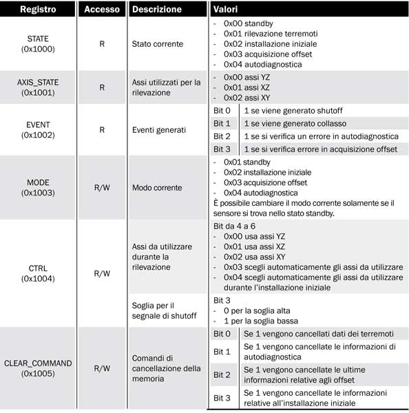
Summary of the status and configuration registers |
| It is worth pointing out that the collapse condition is not checked only when the sensor is powered up, but every time the sensor goes into standby; it also remains possible to force the collapse check by putting the sensor into offset acquisition mode. The data the sensor computes for each seismic event are PGA (Peak Ground Acceleration), SI (Spectral Intensity) and the average ambient temperature at which the event took place. While the computation is running, that is during the earthquake, the instantaneous PGA and SI values can be read from a few specific registers. A self-test function is built into the sensor, very useful to check that the D7S is working correctly, but it has to be started by hand by writing a register over the I²C bus. At every offset acquisition the sensor automatically determines whether the operation succeeded; if it did not, it updates a specific register and so reports the fault. The function pins of the sensor are INT1, INT2 and SET: the first, as already noted, signals the shutoff and collapse conditions, while INT2 tells whether the sensor is in standby, whether it is detecting an earthquake, whether an offset acquisition is under way or whether the self-test function has been started. The last pin, SET, allows the sensor to be put into initial installation mode by an external pulse, without necessarily having to use the I²C bus. When the INT1 pin is taken to logic low by a shutoff or collapse event, the default value, that is logic 1, can only be restored by reading the EVENT register, by running the initial installation procedure or by removing power from the sensor. |
| Breakout boards |
|
Breakout boards are prototyping boards that carry the component already soldered in place, with its connections brought out to pads that are easy to use in terms of pitch and termination; the connections are normally pads on a 2.54 mm pitch, like those of the classic DIP integrated circuits. To help those who would like to use SMD parts but have neither the means nor the skill to solder them, a number of integrated circuits (sensors, switching regulators, battery chargers, linear amplifiers and so on) have been selected and mounted on ready-to-use boards. These breakout boards are both a help for anyone who wants the best of SMD electronics ready to use in a “traditional” format, and for anyone who, while perfectly able to work with SMD parts, needs them available on prototyping boards to add to existing circuits and run tests, that is to build prototypes using the functions of those chips before making the final printed circuit board of a piece of equipment. |
| Documentation and useful links |
Technical details
| Power supply | 3.3 V to 5 V |
|---|---|
| The sensor issues two signals | shutoff and ground collapse |
You may also like…
-
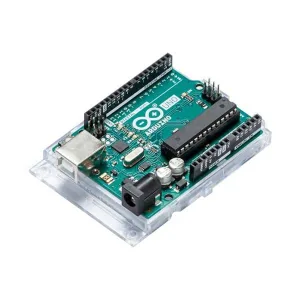 Arduino
Related products
-
 Sensors
 -
 Sensors
 -
 Sensors
 -
 Sensors
 -
 Sensors
 -
 Sensors
 -
 Sensors
 -
 Sensors