
Mini TESLA Speaker – Kit
SKU 8300-MINITESLAKITEAN 8219671095570Item type: KitEducational kits
Description
|
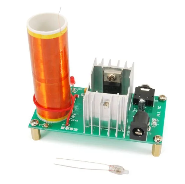
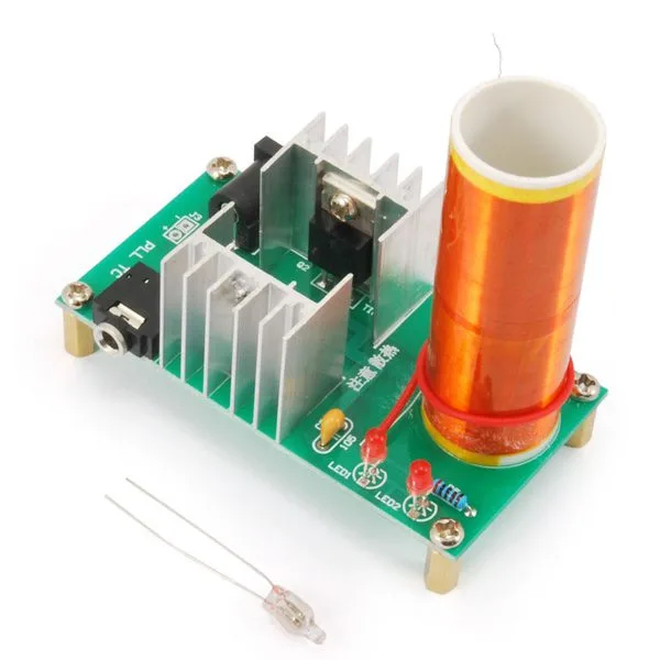
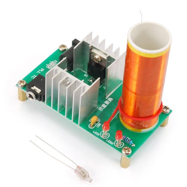
This original kit lets you build a mini Tesla coil that generates high voltage and creates a small lightning arc, which can for instance light a neon lamp simply by bringing it close to the coil. The kit also features an audio input that modulates the generator, switching the arc on and off in time with the music: the audio signal applied to that input excites the arc plasma and turns it into air vibrations, thus reproducing the sound. Power supply: 15 to 24 VDC – 2 A (24 VDC recommended).
|
|
 |
 |
| Technical specifications | |
|
|
| Assembly | |
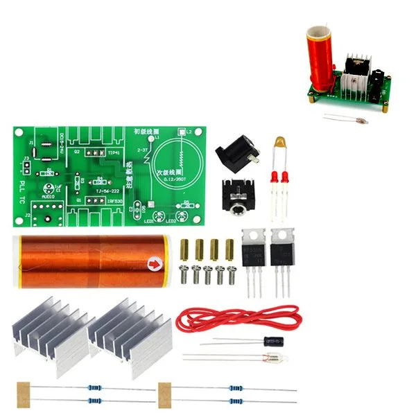
| Start fitting the components with the resistors (R1, R3, R4, R5), then go on with the audio jack socket (J2), the electrolytic capacitor C1 and C2, the LEDs (LED1 and LED2), the power plug (J1) and the power connector J3 (if you prefer to power the circuit from that one); then fit upright, each with its metal face turned outwards from the PCB, the IRF530 MOSFET (Q1) and the TIP41 NPN transistor (Q2), to which you will then fit the 13°C/W aluminium heatsink.
The HT (high voltage) secondary consists of 350 turns of 0.2 mm diameter enamelled copper wire, wound (and held down with adhesive tape so they cannot shift) on a 20 mm plastic cylindrical former about 60 mm long. Gently scrape the enamel off the ends with the blade of a knife or of a pair of scissors (the enamel is off when the wire changes colour, turning more pink than yellowish) so as to remove the insulation and make it easier to solder the end that goes onto the PCB (pad L2). The other end of the coil, the one facing upwards, is left free. We recommend fixing the base of the TESLA coil to the PCB with a cyanoacrylate glue such as Attak. For the primary you have to wind one or two turns of 0.5 mm diameter rigid single-core wire (the red wire supplied in the kit) directly over the HT secondary. The ends of the primary are then soldered to their pads on the PCB, which are marked L1. In use, the printed circuit board must be placed on a base of insulating material, that is dry wood or plastic, so that none of its pads touches metal parts or surfaces. You may also consider a plastic enclosure with the top of the transformer and the free end of the secondary coming out of it, so as to help the discharge or to be able to connect it to a body from which you want the corona discharge to start. |
|
| Testing | |
| Get a mains power supply that delivers 15 V DC at its output, that can supply a current of 2 amps and that has a lead ending in a coaxial jack of a diameter suited to the DC jack socket on the circuit. The polarity of the connector on the board is positive on the centre pin and negative on the outer one, so the power supply jack must match.
The free end wire of the secondary must be led outwards so that, when the circuit is powered, it produces a luminous halo caused by the corona discharge, which ionises the air and can lead to the production of ozone; the electrostatic corona is released from the wire and is visible as a cone-shaped halo, very bright close to the wire and fading as you move away from it. The discharge is accompanied by a characteristic noise, like a rhythmic hiss; both effects are stronger if the ground of the circuit is connected to a large metal sheet laid on the surface the generator rests on, provided that this sheet stays at least ten centimetres or so away from the free electrode of the transformer secondary. Bring a neon lamp or an energy-saving lamp (as long as it is based on a neon tube) close to it and you will see it light up, although more faintly than it would if it were powered normally: this happens because the electric field generated by the transformer ionises the gas inside the lamp. By feeding the signal of an AF source into the audio input we can modulate the electrostatic corona and get the corresponding sound out of the sphere or out of a metal plate: so take a stereo audio cable with two 3.5 mm jacks at its ends and plug one end into the audio output socket of an MP3 player or of a smartphone, tablet or PC holding audio tracks, then plug the other jack into the socket on the circuit, which we keep switched off until all the connections are made. Start playback and switch on the high voltage generator: by changing the volume you will hear the faint sound produced when the audio frequency signal modulates the electrostatic corona (that is, the electric wind). |
|
| Safety precautions | |
|
WARNING!
|
|
Technical details
| Power supply | 15 to 24 VDC |
|---|---|
| Maximum current draw | 2 A |
| High voltage generated | 2.1 kV at 13 Vdc |
| Assembled dimensions (mm) | 76x80x40 |
| R4 | 10 kohm |
| R5 | 2 kohm |
| C1 | 1 µF electrolytic |
| C2 | 1 µF multilayer |
| Q1 | IRF530 |
| Q2 | TIP141 |
| LED2 | 3 mm red LED |
| L1 | short length of wire wound around L2 |
| L2 | TESLA coil |
| J1 | PCB-mount DC plug |
Related products
-
 Educational kits
 -
 Educational kits
 -
 Educational kits
 -
 Educational kits
2x3W Powered Speaker Set with VU Meter and Clear Box
Price range: €15.00 through €35.00 incl. VAT -
 Educational kits
2×5 W Amplifier with Bluetooth and Battery Power – assembled
€8.61excl. VAT€10.50incl. VAT -
 Educational kits
 -
 Educational kits
 -
 Educational kits