
1-Motor DC Driver, 40A – 4 Control Modes
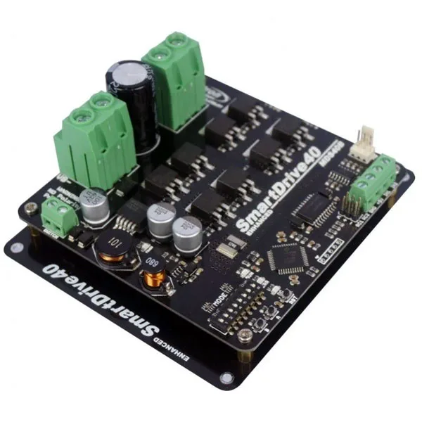
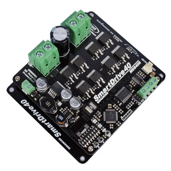
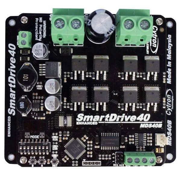
SKU 1686-MDS40BEAN 8219671118767Item type: AssembledControl electronics
Description
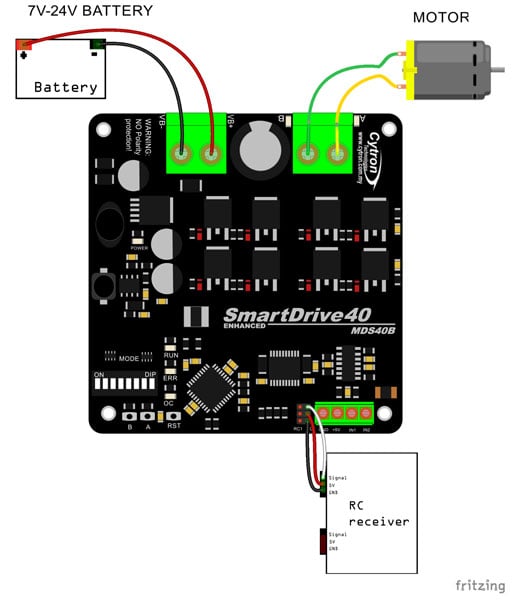
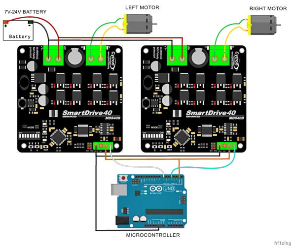
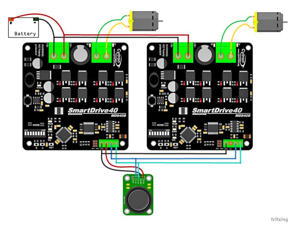
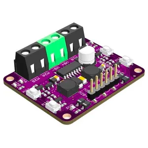
Compact power driver capable of handling 1 DC motor with a supply voltage between 10 VDC and 45 VDC and a maximum current of 40 A (80 A peak). It can be controlled in RC mode (hobby receiver), Analog/PWM from a microcontroller (Arduino or other), Simplified Serial (UART), and Packetized Serial (UART in 4-byte packets). It features a terminal block for motor and power connections, buttons for manual motor operation, inputs for external control, and status LEDs for Power, Error, Running state, and motor. It can be powered with a NiMH or NiCd 9–18 cell battery, LiPo or Li-Ion 3–6 cell battery, 10 V – 45 V lead-acid battery, or 10 V – 45 V power supply. Particularly suitable for robotics, automation, hobby, etc. It can also be connected to another driver of the same type and operate in pairs, allowing control of two motors.
Examples of use
Technical specifications
- – NiMH or NiCd 9–18 cell battery (read the notes in the English manual)
– LiPo or Li-Ion 3–6 cell battery (read the notes in the English manual)
– 10 V – 45 V lead-acid battery
– 10 V – 45 V power supply (read the notes in the English manual) - Operating modes: RC (hobby receiver), Analog/PWM from a microcontroller (Arduino or other), Simplified Serial (UART), and Packetized Serial (UART in 4-byte packets)
- Maximum current: up to 40 A continuous at room temperature (80 A peak for max. 1 second)
- Bidirectional control for a single brushed DC motor
- On-board MOSFETs are switched at 16 KHz for silent operation
- 5 volt output: Yes
- Inputs compatible with 3.3 and 5 volts
- High-amperage screw terminals for battery and motor connection
- Additional terminal to enable or disable the driver (cuts power to the motor driver, eliminating the need for a power switch). Note: it is supplied already jumpered.
- Possibility to add a fan (not included) for better heat dissipation and to further increase the maximum continuous current
- Connector for connecting an RC receiver
- Status LEDs for Power, Error, Running state, and motor
- Reset button to restart the microcontroller after changing the operating mode
Note: It is recommended to use a red AWG14 multi-strand cable and a black AWG14 multi-strand cable for the battery and motor connection.
Documentation and useful links
Technical details
| Board and motor supply | from 10 VDC to 45 VDC |
|---|---|
| Number of motors handled | 1 Brushed DC |
| Thermal and current protection | Yes |
| On-board buttons for manual operation | Yes |
| Reverse polarity protection | NO |
| Actual driver board | 105(L) x 106 (W) x 38 (H) |
| Together with the base | 125 (L) x 107 (W) x 47 (H) |
Related products
-
 Control electronics
 -
 Control electronics
 -
 Control electronics
 -
 Control electronics
 -
 Control electronics
 -
 Control electronics
 -
 Control electronics
 -
 Control electronics