
Open Source quadcopter board
SKU 7100-FT1171EAN 8219671077057Item type: KitControl electronics
Description
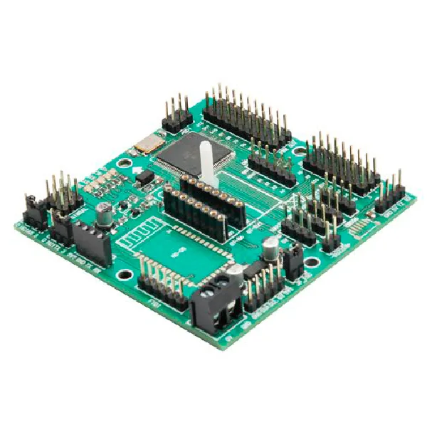
Board based on the Arduino Mega, which allows you to manage the motors of a quadcopter, receive commands from a model aircraft radio control, and support telemetry via smartphone. In addition to the ATmega 2560, programmed with the open-source firmware called MultiWii (which allows controlling multicopters, helicopters, and airplanes), it features 8 motor outputs, 8 inputs for standard RC receivers and compatible with PPM receivers, 4 serial ports for debug / Bluetooth Module / OSD / GPS / telemetry, 3 servo outputs for controlling a gimbal system (pitch, roll, trigger), I²C bus for adding sensors or devices, connector for GPS module, compatible with GY-521, GY-86 and external IMU modules, connector for FTDI USB/serial converter, a 3.3V power stage for any additional devices, and status LEDs. The other fundamental element is the IMU module (Inertial Measurement Unit, i.e., the platform that detects acceleration, movements on the three axes, etc.) available separately and insertable on the dedicated connector of the board. Both the board and the software support various flight configurations: from simple model aircraft to multirotors. The pre-assembled board (only the SMD section) does not include the IMU module, motors, propellers, etc. (see related products).
Flight Terminology
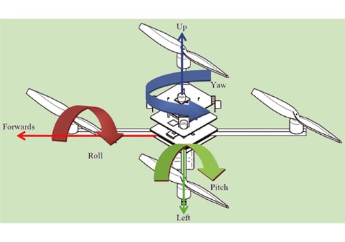
- PITCH: represents the pitch, i.e., the oscillation on the transverse axis.
- ROLL: also called roll, is the term used to define the rotation of the model on its longitudinal axis.
- YAW: tail rotation, i.e., the rotation of the model on its vertical axis.
- PITCH (propeller): indicates the inclination of the propeller blade relative to the plane of rotation.
- CLASS: indicates the category to which the quadcopter belongs, identified by the diagonal distance between two motors in millimeters.
- ESC: acronym for electronic speed controller, i.e., the power driver for brushless motors.
- BEC: acronym for battery eliminator circuit, indicates that the ESC is equipped with an internal voltage regulator.
- PDB: acronym for power distribution board, i.e., the printed circuit used to bring battery power to all ESCs.
- MODE2: mode of using the remote control with throttle and yaw on the left and pitch and roll control on the right.
- MODE1: mode of using the remote control with throttle and yaw on the right and pitch and roll on the left.
- BIND: indicates the association between the remote control and the receiver in RC radio equipment.
- PID: indicates the set of proportional, integral, and derivative parameters of a control.
Loading the BOOTLOADER and Testing the Board
If the board’s microcontroller is not equipped with a bootloader, it must be loaded; for this purpose you can use a dedicated programmer or more simply an Arduino board acting as a programmer. In the latter case, consult Table 2 for the connections to be made between the programmer board and ours. Then open the Arduino IDE and upload the example sketch named ArduinoISP.ino on the Arduino used as a programmer, then from the Tools > Board menu set the target board as “Arduino Mega 2560 or Mega ADK”; after that set Arduino as programmer (Tools > Programmer > Arduino as ISP) and start programming with the command Tools > Burn Bootloader.
When the procedure is complete (it takes a few minutes), disconnect the programmer and interface the board to the PC using a USB/Serial converter connected to the FTDI connector; your board will be seen by the Arduino IDE as an Arduino Mega board. It may happen that at the end of the procedure the error “avrdude: verification error, first mismatch at byte 0x1e000” appears during the re-reading of the written fuses, even if the writing procedure was successful.
The Firmware
The firmware running on the board is not one of the simplest:
in addition to flight stabilization, it must manage alarms, telemetry, position, and much more, so we preferred to use an existing software, completely open source and developed in recent years also with the contribution of enthusiasts online, called MultiWii. It allows controlling multicopters, helicopters, and airplanes; the reference site is www.multiwii.com (the Italian version is www.multiwii.it). The project was born using the gyroscope of a Nintendo Wii Motion Plus (the cheapest and easiest to find at the time) and an Arduino mini pro board, but now it supports a large number of sensors and boards. The firmware is very light and can run on a small ATmega 328, but with all functions activated (navigation and GPS) it is necessary to use an ATmega 2560. The software is managed in the repository https://code.google.com/p/multiwii/. Downloading the software package gives you the software for Arduino and the GUI, written in Processing, to run on the PC to manage settings and telemetry. The software for Arduino uses only system libraries, so its use is immediate with only the Arduino IDE. To configure the board and use telemetry and mission planning, the WinGui software and an Android smartphone application are also available.
You may also like…
-
 Accessories
 -
 Rechargeable batteries
Related products
-
 Control electronics
 -
 Control electronics
 -
 Control electronics
 -
 Control electronics
 -
 Control electronics
 -
 Control electronics
 -
 Control electronics
 -
 Control electronics