
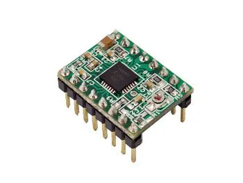
A4988 stepper motor driver board
SKU 7350-3DDRIVEREAN 8219671031974Control electronics, Control electronics
Description
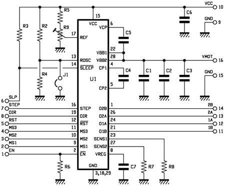
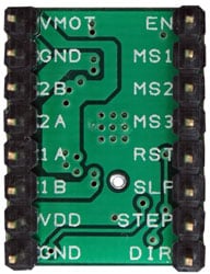
Based on the Allegro A4988 chip, this small driver can control a single bipolar stepper motor with a max current of 2 A. Five motor control modes can be selected: full step, 1/2 step, 1/4 step, 1/8 step, and 1/16 step. Each time a high-level pulse arrives on the STEP pin (minimum allowable duration is 1 µs), unless otherwise set, the outputs 1A, 1B, 2A, and 2B provide the pulses to command the motor rotor movement by one step or fraction, depending on how the MS1, MS2, MS3 inputs are set. The SLEEP pin activates sleep mode (logic active and drivers off), the RESET pin resets the controller that governs the drivers and sets the motor command outputs (1A, 1B, 2A, 2B) to logic zero even if STEP continues to receive pulses. The logic is TTL-compatible; however, the module accepts control input voltages up to 0.7 times the voltage applied between pin 2 (Vcc) and ground (GND); the low level must not exceed 0.3xVcc. The maximum output current can be set via the onboard trimmer. Logic supply: 3.3 to 5.5 V, motor supply: 8 to 35 V.
WARNING! The board is supplied with all SMD components already mounted, while the other components (strip, etc.) must be mounted by the customer.
Electrical schematic and pinout
Stepper motor connections
The driver can control four-, six-, and eight-wire stepper motors if connected correctly. For motor connections in bipolar configuration, see below.
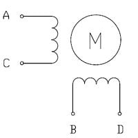
TWO-PHASE BIPOLAR STEPPER MOTOR – 4 WIRES:
Connect terminal A to the driver output marked 1A, terminal C (same phase) to output 1B – connect terminal B to output 2A, terminal D to output 2B.
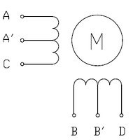
TWO-PHASE UNIPOLAR STEPPER MOTOR – 6 WIRES:
Make the same connection as the 4-wire bipolar motor, leaving terminals A’ and B’ unconnected.
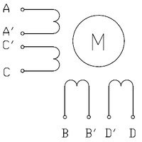
TWO-PHASE UNIPOLAR STEPPER MOTOR – 8 WIRES:
To connect the phase coils in parallel, connect terminals A and C’ to the driver output marked 1A, terminals A’ and C to output 1B, terminals B and D’ to output 2A, and terminals B’ and D to output 2B. To connect the phase coils in series, connect terminals A’ and C’ together, and B’ and D’ together. Terminals A, C, B, and D must be connected to the driver as in the 4-wire bipolar motor connection.
You may also like…
-
 Cooling & heating
 -
 Control electronics
 -
 Control electronics
Related products
-
 Control electronics
 -
 Control electronics
 -
 Control electronics
 -
 Control electronics
 -
 Control electronics
 -
 Control electronics
 -
 Control electronics
 -
 Control electronics