| Oscilloscope function |
| Acquisition |
Real-time sample rate |
1 GSa/s(single channel) 500 MSa/s(two channels) |
| 250 MSa/s(three/four channels); |
| Note:digital channel 12,34 open at the same time,it is considered as one channel |
| Peak detection |
Analog channel 4ns |
| Note:digital channels don’t support |
| Average mode |
Analog channel |
| All channels reach N time samples at the same time,N can be selected from
2、4、8、16、32、 64、128、256、512 and 1024. |
| Note:digital channels don’t support |
| High resolution |
Up to 12bit |
| Note:digital channels don’t support |
| Minimum test pulse width |
8ns |
| Memory depth |
Single channel 64M |
| Two channels 32M |
| Three,four channels 16M |
| Input |
Channel quantity |
4 analog channels |
| Note:data channels can’t be opened |
| 3 analog channels |
| Note:digital channel LA1/LA2/LA3/LA4/LA1LA2/LA3LA4 |
| 2 analog channels |
| Note:digital channels infinitize |
| 1 analog channel |
| Note:digital channels infinitize |
| 0 analog channel |
| Note:digital channels infinitize |
| Input coupling |
DC、AC or GND |
| Note:digital channels don’t support |
| Input impedance,DC coupling |
Analog channel |
| 25pF±3 pF,1MΩ±2% |
| Digital channel |
| (300KΩ±2%) ,(8 pF±3 pF) |
| Supported probe attenuation factor |
Analog channel 1X、10X、100X、1000X |
| Voltage classes |
300V CAT II |
| Maximum input voltage |
Analog channel 300VRMS (10X) |
| Digital channel -25V~25V |
| Horizontal |
Waveform interpolation |
(sin x)/x |
| Maximum record length |
Single channel maximum 64M |
| Two channels maximum32M |
| three/four channels maximum 16M |
| Horizontal scale range |
DSO6084 DSO6104 |
| 2ns/div~100s/div 1, 2, 5 step by step |
| Time base mode |
Y-T、X-Y、Roll |
| X-Y number |
Channel 1,2 1 XY channel、channel3 4 1 XY channel |
| Zero offset |
±0.5 div× minimum time base gear |
| Sample Rate and |
±25ppm |
| Delay Time Accuracy |
| Clock drifting |
≤±5 ppm/year |
| Delta Time Measurement |
single,“acquisition”mode |
| Accuracy |
| (Full Bandwidth) |
±(1 sample interval+100ppm×reading+0.6ns) |
| >16 times averages |
| ±(1 sample interval+100ppm×reading+0.4ns) |
| Sample interval=sec/div÷200 |
| Vertical |
Bandwidth(-3db) |
6084 |
6104 |
6204 |
| 80MHz |
100MHz |
200MHz |
| Vertical resolution |
Analog channel 8bit |
| Digital channel 1bit |
| Vertical scale range |
nput BNC position is 500μV/div~10V/div |
| Position range |
500μV/div to 120mV/div,±1V |
| 122mV/div to 1.2V/div,±10V |
| 1.22V/div to 10V/div,±50V |
| Optional analog bandwidth limitation |
Typical 20MHz |
| Bass response(-3db) |
In BNC position is≤10Hz |
| Rising time in BNC position,typical |
6084 |
6104 |
6204 |
| ≤4.4ns |
≤3.5ns |
≤1.8ns |
| Vertical gain accuracy |
In “normal” or “average” acquisition mode,the accuracy o
f 10V/div to 10mV/div is ±3% |
| In “normal” or “average” acquisition mode,the accuracy of
5mV/div to 500uV/div is ±4%. |
| DC offset accuracy |
±0.1 div±2 mV±1% offset value |
| The isolation of channels |
DC maximum bandwidth:>40 dB |
| Note: Bandwidth reduced to 6MHz when using a 1X probe |
| Trigger |
Trigger level range |
±5 divisions from the center of the screen |
| Trigger mode |
auto、general、single |
| Level |
CH1~CH4 |
±4 divisions from the center of the screen |
| Holdoff range |
8ns~10s |
| Trigger level accuracy |
CH1~CH4 |
0.2 div×volts/div within ±4 divisions
from the center of the screen |
| Edge trigger |
Slope |
Rising edge,falling edge,rising or falling edge |
| Signal source |
CH1~CH4, |
| D1.0~D1.3, |
| D2.0~D2.3, |
| D3.0~D3.3, |
| D4.0~D4.3 |
| Pulse width trigger |
Polarity |
Positive polarity,negative polarity |
| Condition(When) |
<,>, !=, = |
| Signal source |
CH1~CH4, |
| D1.0~D1.3, |
| D2.0~D2.3, |
| D3.0~D3.3, |
| D4.0~D4.3 |
| Pulse width range |
8ns ~ 10s |
| Video trigger |
Signal standard |
NTSC, PAL |
| Signal source |
CH1~CH4 |
| Synchronization |
Scanning line、line number、odd field、even field、all field |
| Slope trigger |
Slope |
rise,fal |
| condition(When) |
<,>, !=, = |
| Signal source |
CH1 ~ CH4 |
| Time range |
8ns ~ 10s |
| Overtime trigger |
Signal source |
CH1~CH4, |
| D1.0~D1.3, |
| D2.0~D2.3, |
| D3.0~D3.3, |
| D4.0~D4.3 |
| Polarity |
Positive polarity,negative polarity |
| Time range |
8ns ~ 10s |
| Window trigger |
Signal source |
CH1~CH4LA1~LA4 |
| Pattern trigger |
Pattern |
0:low level;1:high level;X:ignore; |
| Level(signal source) |
CH1~CH4 |
| Interval trigger |
Slope |
rise,fall |
| condition(When) |
<,>, !=, = |
| Signal source |
CH1~CH4, |
| D1.0~D1.3, |
| D2.0~D2.3, |
| D3.0~D3.3, |
| D4.0~D4.3 |
| Time rangeTime range |
8ns ~ 10s |
| Delay trigger |
Edge type |
Rising edge,falling edge |
| Signal source |
CH1~CH4 |
| condition(When) |
<,>, !=, = |
| Time range |
8ns ~ 10s |
| Set up hold trigger |
Edge type |
Rising edge,falling edge |
| Signal source |
CH1~CH4 |
| condition(When) |
<,>, !=, = |
| Time range |
8ns ~ 10s |
| Runt trigger |
Polarity |
Positive polarity,negative polarity |
| Condition(When) |
<,>, !=, = |
| Signal source |
CH1~CH4 |
| Time range |
8ns ~ 10s |
| UART trigger |
condition(When) |
start、stop、data、odd-even check、reception error |
| Signal source(RX/TX) |
CH1~CH4, |
| D1.0~D1.3, |
| D2.0~D2.3, |
| D3.0~D3.3, |
| D4.0~D4.3 |
| Data format |
Hex(hexadecimal) |
| Data length |
1 byte |
| Data bit width |
5 bit, 6 bit, 7 bit, 8 bit |
| Odd-even check |
none、odd、even |
| Free level |
high、low |
| Baud rate (optional) |
110/300/600/1200/2400/4800/9600/14400/19200/38400/57600
/115200/230400/380400/460400 bit/s |
| Baud rate(user-defined) |
300bit/s~334000bit/s |
| LIN trigger |
condition(When) |
Interval field、synchronization field、ID field、synchronization error
、identifier、IDand data |
| Signal source |
CH1~CH4, |
| D1.0~D1.3, |
| D2.0~D2.3, |
| D3.0~D3.3, |
| D4.0~D4.3 |
| Data format |
Hex(hexadecimal) |
| Baud rate(optional) |
110/300/600/1200/2400/4800/9600/14400/19200/38400/57600
/115200/230400/380400/460400 bit/s |
| Baud rate(user-defined) |
300bit/s~334000bit/s |
| CAN trigger |
condition(When) |
Start bit、remote frame ID、data frame ID、frame ID、remote frame data、data frame data、wrong frame、all errors、answer error、overload frame |
| Signal source |
CH1~CH4 |
| Data format |
Hex(hexadecimal) |
| Baud rate(optional) |
10000, 20000, 33300, 500000, 62500, 83300, 100000, 125000, 250000, 500000, 800000, 1000000 |
| Baud rate(user-defined) |
5kbit/s~1Mbit/s |
| SPI trigger |
Signal source |
CH1~CH4, |
| D1.0~D1.3, |
| D2.0~D2.3, |
| D3.0~D3.3, |
| D4.0~D4.3 |
| Data format |
Hex(hexadecimal) |
| Data bit width |
4, 8, 16, 24, 32 |
| IIC trigger |
Signal source (SDA/SCL) |
CH1~CH4, |
| D1.0~D1.3, |
| D2.0~D2.3, |
| D3.0~D3.3, |
| D4.0~D4.3 |
| Data format |
Hex(hexadecimal) |
| Data index |
0~7 |
| opportunity(condition) |
Start bit、stop bit、no response、address、data、restart |
| Measurement |
cursor |
Voltage difference between cursors △V |
| Time difference between cursors △T |
| Reciprocal of △T,in Hertz(1/△T) |
| Auto measurement |
frequency、period、mean、peak-to-peak、RMS、minimum、mixmum、rising time、falling time、+ width、- width、base、top、middle、amplitude、overshoot、preshoot、rising edge phase difference、falling edge phase difference、+ duty、- duty、period mean、PRMS、FOVshoot、ROVshoot、BWIDTH、FRF、FFR、LRR、LRF、LFR、LFF |
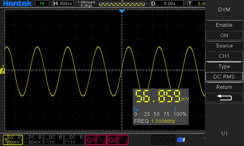
| DVM |
Data source |
CH1,CH2,CH3,CH4 |
| Measurement type |
DC effective value |
| AC effective value |
| DC |
| Frequency meter |
hardware 6 bits frequency meter |
| Arbitrary waveform generator |
| Arbitrary waveform generator(for oscilloscopes with signal source channels) |
Channel number |
2channels |
| Sample rate |
200MSa/s |
| Vertical resolution |
12 bits |
| Maximum frequency |
25 MHz |
| Standard waveforms |
sin、square、pulse、triangular,noise、DC |
| Sinc、index、semi-distortion、lorentz,dual tone multiple frequency,gauss,ECG |
| Arbitrary waveform |
Arb1,Arb2,Arb3,Arb4 |
| Sin |
Frequency range |
0.1Hz~25MHz |
| square/pulse |
Frequency range |
0.1Hz~10MHz |
| triangular wave |
Frequency range |
0.1Hz~1MHz |
| Sampling wave |
Frequency range |
0.1Hz~1MHz |
| Index |
Frequency range |
0.1Hz~5MHz |
| Semi-distortion |
Frequency range |
0.1Hz~1MHz |
| lorentz |
Frequency range |
0.1Hz~1MHz |
| Dual tone multiple frequency |
Frequency range |
0.1Hz~1MHz |
| Gauss |
Frequency range |
0.1Hz~1MHz |
| ECG |
Frequency range |
0.1Hz~1MHz |
| Arbitrary wave |
Frequency range |
0.1 Hz to 10 MHz |
| Waveform length |
8KSa |
| Frequency |
accuracy |
100 ppm(<10 kHz) 50 ppm(>10 kHz) |
| resolution |
0.1 Hz or 4 bits,take the greater one |
| Amplitude |
Output range |
10mV~7Vp-p(high impedance) |
| 5mV~3.5Vp-p(50Ω) |
| DC offset |
range |
±3.5 V,high impedance |
| ±1.75 V,50 Ω |
| resolution |
100 μV or 3 bits,take the greater one |
| accuracy |
2%(1 kHz) |
| Output impedance |
50 Ω |
| Logic analyzer |
| Logic analyzer |
Input impedance,DC coupling |
Digital channel |
| (300KΩ±2%) ,(8 pF±3 pF) |
| Threshold value |
4 channels in 1 group adjustable threshold value |
| Threshold option |
TTL(1.4 V) |
| 5.0 V CMOS(+2.5 V) |
| 3.3 V CMOS(+1.65 V) |
| 2.5 V CMOS(+1.25 V) |
| 1.8 V CMOS(+0.9 V) |
| ECL(-1.3 V) |
| PECL(+3.7 V) |
| LVDS(+1.2 V) |
| 0V |
| User-defined |
| Threshold range |
±7.0V,10mV step by step |
| Threshold accuracy |
±(100mV+3% threshold setting) |
| Dynamic range |
±5.0V+ threshold |
| Minimum voltage swing |
500 mVpp |
| Vertical resolution |
1 bit |
| General specifications |
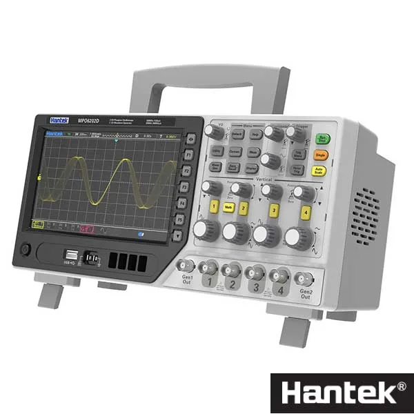
| Display |
Display type |
7″TFT diagonal liquid crystal |
| Display resolution |
800(horizontal)*480(vertical)pixels |
| Display colour |
16 million colours(24 bits true colour) |
| Persistence time |
minimum、1 s、5 s、10 s、30S、infinite |
| Display type |
dot、vector |
| Display mode |
Color temperature,gray scale |
| Display brightness |
adjustable |
| Grid type |
adjustable |
| Grid brightness |
adjustable |
| Interface |
Standard interface |
USB Host,USB Device,LAN, EDU signal WIFI |
| Aux(trigger output/PassFail )–only EDU with this interface |
| Optional interface |
PassFail |
| UART |
| HDMI |
| General specifications |
Probe compensator output |
| Output voltage ,typical |
about 2Vpp input≥1MΩ load |
| frequency、typical |
1kHz |
| Power supply |
100-120VACRMS(±10%),45Hz to 440Hz,CATⅡ |
| 120-240VACRMS(±10%),45Hz to 66Hz,CATⅡ |
| Power consumption |
<30W |
| Fuse |
T,3.15A,250V,5x20mm |
| Operating temperature |
0~50 °C (32~122 °F) |
| Storage temperature |
-40~+71 °C (-40~159.8 °F) |
| Humidity |
≤+104℉(≤+40°C): ≤90% relative humidity |
| 106℉~122℉ (+41°C ~50°C): ≤60% relative humidity |
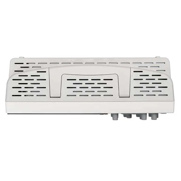
| Cooling method |
convection |
| Altitude |
Operating and nonoperating |
3,000m(10,000 feet) |
| Mechanical shock |
Random vibration |
0.31 g RMS from 50Hz to 500Hz, |
| 10 minutes on each axis |
| Nonoperating |
2.46g RMS from 5Hz to 500Hz, |
| 10 minutes on each axis |
| Operating |
50g,11ms,half-sine wave |
| Mechanical |
Size |
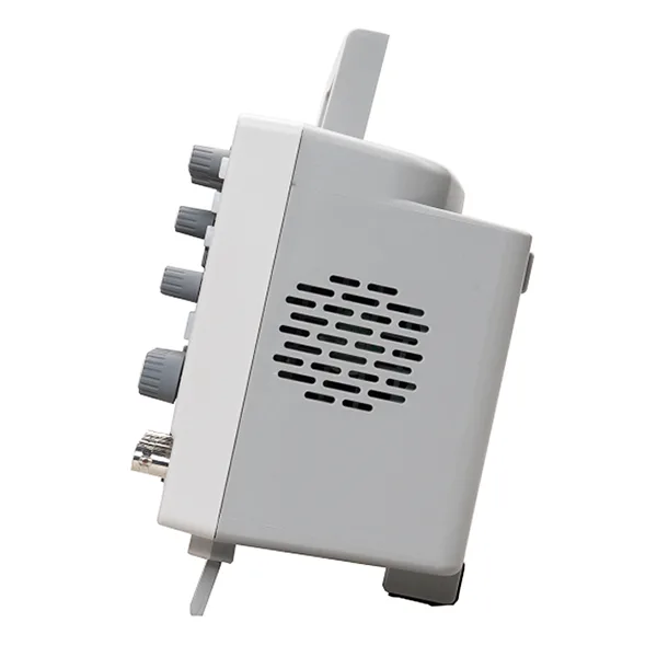
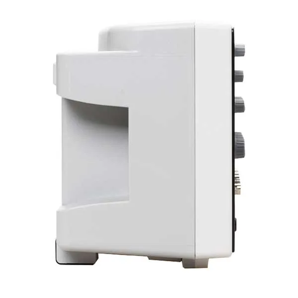
318 x 140 x 150mm(length x width x height) |
| Weight |
2900g |

 Oscilloscopes & dataloggers
 Test & measurement
 Function generators
 Oscilloscopes & dataloggers
 Oscilloscopes & dataloggers
 Function generators
 Oscilloscopes & dataloggers
 Oscilloscopes & dataloggers