
DM Board ICS GSM Demo Board
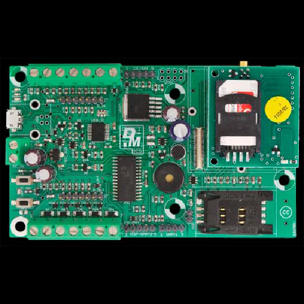
SKU 7302-DMBOARDICSEAN 8219671069731Item type: AssembledGSM/GPRS
Description
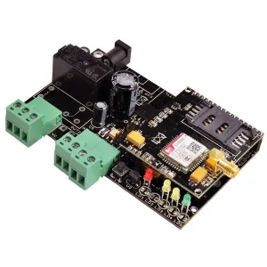
Based on the Microchip 18F26K22 microcontroller with XLP (eXtreme Low Power) technology, the DM Board ICS is an open source board that allows you to control and command whatever you want, anywhere and in the way you want. The idea is based on the creation of a board (DM Board ICS) equipped with a series of peripherals, programmable in a graphical environment. The board has 5 inputs and 5 outputs; both inputs and outputs can operate at 3.3 V or 12 Vdc depending on the connection point.
The outputs are implemented through open drain stages capable of directly driving relays. The board also includes a buzzer that can be used to generate acoustic signals. In addition, two buttons and an LED are available, manageable directly from the firmware loaded in the board’s microcontroller. Remote control of the DM Board ICS is entrusted to a GSM module equipped with a microphone for ambient listening and an audio output for voice calls. For communication with the outside world, the board has a USB 2.0 port (in device mode), an I²C-Bus link, and two UARTs shared with the GSM module and the USB port. Finally, the DM Board ICS contains a circuit for detecting the supply voltage, which allows monitoring the charge state of any battery used to power the board in case of blackout or in applications where mains voltage is missing. In fact, the DM Board ICS is designed to be powered at 12 Vdc through a battery, but it can also work fine at lower voltages, as long as they are continuous.
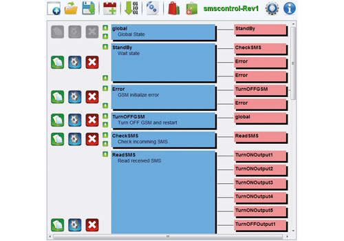
The hardware is designed for low power consumption, drawing only 20 µA, thanks to the specific mode provided by the microcontroller, which nevertheless remains “listening” for any interrupts that, when they arrive, bring it back to normal mode. All on-board peripherals include components for protection against electrostatic discharges. The development software created for this purpose is called DM Design and is practical, fast, and intuitive: programming applications does not require knowledge of specific programming languages, because with simple predefined blocks it allows you to control all board functions. This is done simply by joining software blocks, each of which manages a single board function.
Programming is therefore supported through the integrated development environment DM Design, which, in addition to creating the firmware, allows programming the microcontroller on the board. Furthermore, from a dedicated online store (DM Store) accessible directly from DM Design (www.dmboard.it/), it is possible to download ready-made programs in source format, which can be modified and/or inserted directly into the DM Board ICS. The DM Store is a space on the site where all users can upload their projects, sharing them with the community; thus everyone can download the program that best suits their needs, modify it, or use it immediately on their DM Board ICS. Thanks to user sharing, for complete management of the DM Board ICS it may not be necessary to write a single line of code, since, simply by following guided procedures, DM Design can automatically generate the code to download to the board.
The DM Board project consists of the DM Board ICS board and a firmware development software for hardware management, namely DM Design. It can be used as a wired alarm that uses simple magnetic contacts, or, through wired/wireless converters, a wireless alarm that uses the most common radio sensors; the alarm must report, via a siren and by sending an SMS, an attempted break-in or intrusion into the protected environment.
Warning: The GSM module code FT900M, essential for product operation, is not included and must be purchased separately.
The board is supplied already assembled and does not include the following products available separately: assembled cellular modem code FT900M, mini-stick GSM antenna code ANTSMAGSM, and adapter cable code CVANT-SMA.
Warning! The connector for the radio receiver is currently not managed.
DM Design Development Environment
Technical Specifications
- 2 Buttons and 1 LED: manageable directly from the firmware loaded in the board’s microcontroller
Technical details
| Power supply | 12 Vdc - 2 A |
|---|---|
| Inputs | 5 operating at 3.3 V or 12 V |
| Outputs | 5 open drain operating at 3.3 V or 12 V |
| Buzzer | 1 for generating acoustic signals |
| Microphone for ambient listening | yes |
| Audio output | for voice calls |
Related products
-
 GSM/GPRS
 -
 GSM/GPRS
 -
 GSM/GPRS
 -
 GSM/GPRS
 -
 GSM/GPRS
 -
 Other security
 -
 Gas & smoke detectors
 -
 GSM/GPRS