
Miniature twilight switch
SKU 7100-FT972KEAN 8219671050425Item type: KitControllers & drivers
Description
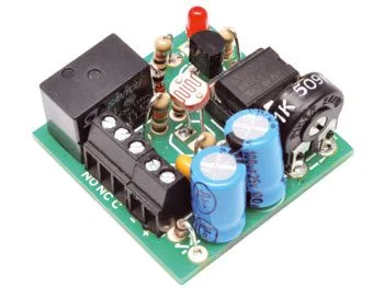
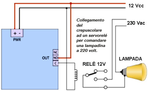
Based on an operational amplifier wired as a comparator, a photoresistor detects the ambient light level and can switch on lamps or other electrical loads when brightness falls below an adjustable threshold. It features a relay output for controlling low-voltage loads (for 220 Vac loads, use the changeover contact to drive a suitably rated relay). The photoresistor can be mounted on the PCB (it is non-polarized, so you can connect it either way) on either side, or mounted externally using two short lengths of insulated wire, provided they are no longer than two or three meters. The relay can switch currents up to 500 mA in circuits operating at no more than 60 Vdc or 120 Vac; to control a lamp, use the C and NO contacts as a switch. A diode protects against reverse polarity at the input terminals. Power supply: DC voltage, preferably stabilized (otherwise the comparator may oscillate near the threshold voltage, despite the RC filter network), between 9 and 12 volts. Dimensions: 29x29x15 mm.

Application with Relay
Circuit Diagram
Operation…
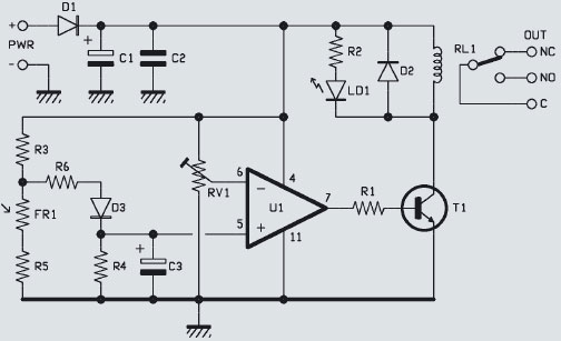
To detect illumination, we use the photoresistor labeled FR1, which has maximum resistance in darkness (about 1 MΩ) and minimum resistance (a few hundred ohms) when exposed to strong light; this characteristic allows us to detect the ambient light level based on the resistive value of the component, i.e., by placing the photoresistor in a voltage divider, we can refer to the voltage at its output. Using a divider allows us to use a comparator to define the voltage threshold corresponding to a certain brightness level at which the relay must be energized. A trimmer in the comparator reference network lets us freely set the light level at which the twilight switch activates.
Let’s look at the operation in detail, assuming we start from total darkness; in this case, the resistance of FR1 is much higher than that of R3 and R5, so the voltage at the node formed by it with R3 and R6 is approximately equal to that measured after diode D1, and thus the same as that powering IC U1. If the wiper of trimmer RV1 is far from the positive line (i.e., the cathode of D1), the voltage at the inverting input of the op-amp is lower than that at the non-inverting input, so the output of U1 goes high and biases transistor T1, whose collector conducts current and simultaneously energizes the relay coil and the R2/LD1 network, lighting the LED (thus signaling the activation of the twilight switch output) and energizing RL1. The changeover contact closes between C and NO, completing the circuit of the connected load.
When ambient light increases, the voltage brought by R6 and D3 to pin 5 of U1 begins to drop, because the resistance of the photoresistor progressively decreases in relation to the intensity of light striking its sensitive surface; at a certain point, the non-inverting input falls below the potential at the inverting input set by the wiper of RV1, and the comparator flips its output, which goes low and cuts off transistor T1. Now the LED turns off and the relay armature drops. If brightness decreases again, pin 7 of U1 returns high and the relay energizes again (and the LED turns back on).
The point at which the relay energizes and the LED lights is set by trimmer RV1: moving the wiper toward ground reduces the voltage at which the comparator returns to rest, so more light is required to deactivate the relay; conversely, moving toward the cathode of D1 raises the voltage that pin 5 must reach, so to trigger the relay the photoresistor must present higher resistance, meaning it must be darker.
In the comparator circuit, note diode D3 (it carries the potential from R6 to the op-amp, preventing C3 from discharging through it), inserted to create, together with capacitor C3, a sort of anti-chatter network essential to avoid both the comparator switching on a very brief light variation (e.g., a bird flying over or a person or car passing) and, during transitions from dark to light and vice versa, the relay chattering because the comparator switches repeatedly as the photoresistor’s resistance oscillates around the switching point. This latter situation could also be avoided by positive feedback on U1, creating a hysteresis circuit (i.e., with two different switching thresholds), but here we opted for a normal comparator, filtering the voltage from the divider containing the photoresistor with an RC network.
Related products
-
 Controllers & drivers
 -
 Controllers & drivers
 -
 LED & strip drivers
 -
 Controllers & drivers
 -
 Controllers & drivers
 -
 Controllers & drivers
 -
 Controllers & drivers
 -
 Controllers & drivers