
Arduino I/O expander shield
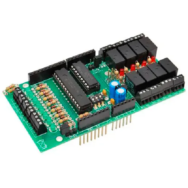
SKU 7100-FT1079KEAN 8219671062435Item type: Assembled, Kit, Shields & add-onsArduino, Arduino compatible
Description
I/O expansion shield for Arduino based on the MCP23017 chip manufactured by Microchip. It features 8 digital inputs, each with a protection diode, a pull-up resistor and an LED; 8 relay outputs with corresponding status LEDs.
Communication with the MCP23017 is based on the I²C bus, so the library uses Arduino’s “Wire.h”. The I²C bus is made up of 2 pins (SDA, i.e. data, and SCL, i.e. clock); on the IC they are available on pins 13 and 12, brought out to the corresponding pins on the Arduino board. The shield provides the option (via jumper) to bring the MCP23017 interrupt pin (INTB, pin 19) to two different Arduino pins (D2 or D4) to adapt it as closely as possible to real-world use. The I²C bus address of the MCP23017 is selected via DIP switch, allowing up to 8 different shields to be connected without interfering with each other. The kit includes all components, the drilled and silkscreened PCB, and all hardware.
Arduino I²C I/O Expander Shield Library
We have developed an Arduino software library that provides all the routines needed to detect connected shields and manage their I/O (you can download this library from this page). Communication with the MCP23017 is based on the I²C bus, so the library uses Arduino’s “Wire.h”; there is a “begin(int i2cAddress)” function to initialize a single shield identified by I²C address, and also an “init()” to properly program the chip’s internal registers according to our needs, and finally a “pinMode(int pin, int mode)” to indicate whether individual I/O pins are inputs or outputs. In addition to the initialization functions, the instructions we are particularly interested in are “digitalRead(int pin)”, “digitalWrite(int pin, int val)”, “digitalWordRead()” and “digitalWordWrite(word w)”, which respectively allow reading the state of a single input pin, writing a single output pin, reading the state of all input pins (8 in our case), and finally writing the state of all output pins (again 8).
Input management can be done via interrupts; there is therefore a dedicated “pinDisableINT(int pin)” function that allows configuring a single pin as an interrupt generator or not (in particular applications it might be useful to have the option of not setting all input pins as interrupt generators, but doing so selectively).
Documentation and useful links
You may also like…
-
 Arduino
Related products
-
 Arduino
 -
 Control electronics
 -
 Arduino compatible
 -
 Displays
 -
 Arduino compatible
 -
 Development systems
 -
 Arduino
 -
Sale!
 Arduino compatible