
Bipolar Stepper Motor Driver 2.2A
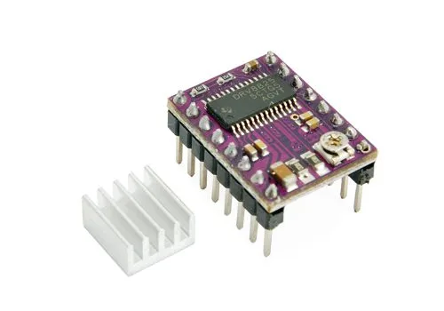
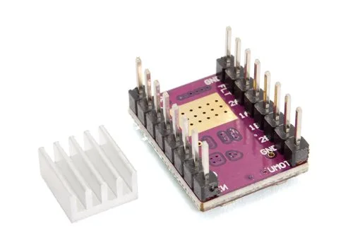
SKU 8218-DRV8825EAN 8219671063340Item type: AssembledControl electronics
Description
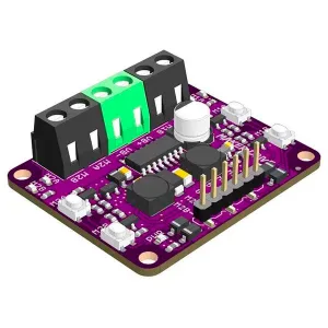
Based on the Texas Instruments DRV8825 chip, this small driver can control a single bipolar stepper motor with a maximum current of 2.2 A per phase. Six motor control modes are selectable: full-step, 1/2-step, 1/4-step, 1/8-step, 1/16-step, and 1/32-step. The maximum output current can be set via the onboard trimmer. Control logic supply: 2.5 to 5.5 V; motor supply: 8.2 to 45 V. Dimensions (mm): 20 x 15, weight: 1.6 g. It can interface directly with 3.3 V and 5 V systems and features load short-circuit protection. Dimensions, pinout, and control interface are compatible with the 3DDRIVER.
Warning! The board is supplied with all SMD components already mounted, except for the headers.
7350-3DDRIVER
- Motor supply:
– min. 8 V
– max. 35 V - Control logic voltage:
– min. 3 V
– max. 5.5 V
8218-DRV8825
- Motor supply:
– min. 8.2 V
– max. 45 V - Current per phase:
– continuous operation: 1.5 A (without heatsink)
– maximum: 2.2 A (with heatsink) - Control logic voltage:
– min. 2.5 V
– max. 5.25 V - Motor control modes: 6 (full-step, 1/2-step, 1/4-step, 1/8-step, 1/16-step, and 1/32-step)
Connections
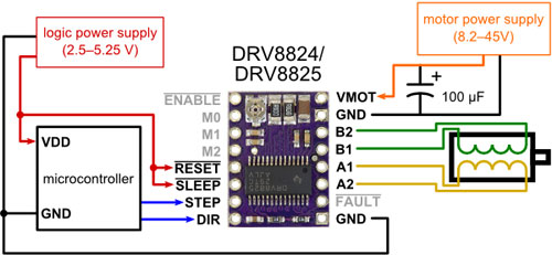
Warning!
- This driver uses low-ESR ceramic capacitors, making it susceptible to destructive LC voltage spikes. These spikes can exceed the maximum rated voltage of 45 V and permanently damage the driver, even when the motor supply voltage is 12 V. One way to protect the driver from such spikes is to place a large (at least 47 µF) electrolytic capacitor between the VMOT pin and GND.
- Connecting or disconnecting a stepper motor while the driver is powered can damage the driver.
Verifying/Adjusting the current set via Vref
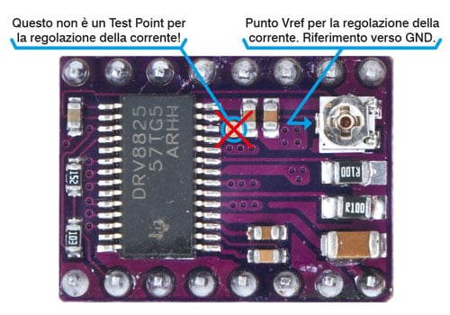
The trimmer allows adjusting the maximum current the driver will supply to the motor.
Set the tester to DC voltage, then place the red probe on the Vref point and the black probe on GND. By adjusting the trimmer, the measured voltage will vary and represents the current that will be delivered according to the formula I = Vref * 2; therefore, if 0.9 V is measured, the driver will deliver 1.8 A.
Motor connections
The driver can control four-, six-, and eight-wire stepper motors if they are connected correctly. For bipolar configuration connections, see below.
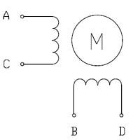
TWO-PHASE BIPOLAR STEPPER MOTOR – 4 WIRES:
Connect terminal A to the driver output marked 1A, terminal C (same phase) to output 1B – connect terminal B to output 2A, terminal D to output 2B.
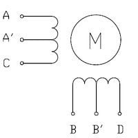
TWO-PHASE UNIPOLAR STEPPER MOTOR – 6 WIRES:
Make the same connections as for the 4-wire bipolar motor, leaving terminals A’ and B’ unconnected.
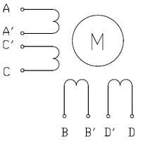
TWO-PHASE UNIPOLAR STEPPER MOTOR – 8 WIRES:
To connect the phase windings in parallel, connect terminals A and C’ to the driver output marked 1A, terminals A’ and C to output 1B, terminals B and D’ to output 2A, and terminals B’ and D to output 2B.
To connect the phase windings in series, connect terminals A’ and C’ together, and B’ and D’ together. Terminals A, C, B, and D must be connected to the driver as in the 4-wire bipolar motor connection.
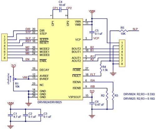
SCHEMATIC DIAGRAM
Documentation and useful links
Technical details
| continuous operation | 1 A (without heatsink) |
|---|---|
| maximum | 2 A (with heatsink) |
| Motor control modes | 5 (full-step, 1/2-step, 1/4-step, 1/8-step, and 1/16-step) |
You may also like…
-
 Control electronics
 -
 Control electronics
Related products
-
 Control electronics
 -
 Control electronics
 -
 Control electronics
 -
 Control electronics
 -
 Control electronics
 -
 Control electronics
 -
 Control electronics
 -
 Control electronics