
2-Channel GSM Remote Control Unit, 4G/LTE
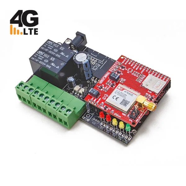
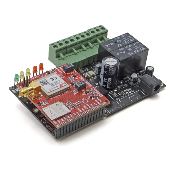
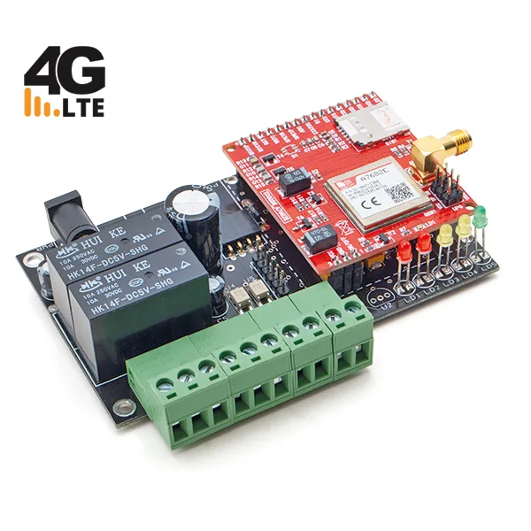
SKU 8100-TDG133_4GEAN 8057190730158Item type: AssembledGSM/GPRS
Description
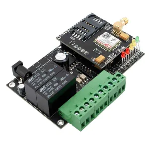
Bidirectional remote control system based on the SIMCom A7682E GSM/4G module, enabling activations and controls via SMS and calls on the GSM network.
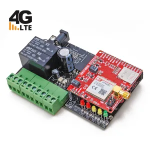
The device is compatible with 4G radio bridges, ensuring full coverage where the old 2G/3G network has been decommissioned. This GSM remote control system features two relay outputs, which can operate in monostable or bistable mode, and two opto-isolated alarm inputs.
Up to 8 numbers can be stored for sending alarms, and up to 200 numbers for the gate opening function. All system settings can be configured via SMS or, optionally, via a local PC interface using the FT782M interface.
The power supply for the GSM remote control system can range from 9 to 32 Vdc, with a maximum current draw of 1A (power supply not included). The package includes the device already assembled and tested with the A7682E GSM/4G module and a stub-style GSM antenna with connection cable.
This bidirectional remote control system allows control of boilers or other connected devices, although it does not have a specific temperature control function.
Important! To use the call service in areas covered by 4G LTE, you must have a SIM card with data and voice traffic compatible with VoLTE. Make sure, by contacting your telephone operator, that this technology is available for the SIM in use. Without this service, the remote control would only work in SMS mode.
Application Example
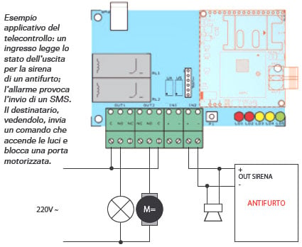
Typical Applications
In SMS mode:
– Burglar alarm systems for residential and industrial buildings
– Burglar alarm systems for vehicles
– Control of air conditioning/heating systems
– Control of pumps and irrigation systems
– Control of industrial plants
– Boiler control
In voice call / gate opening mode (Output 1):
– Gate opening
– Access control
– Reset circuits
Technical Specifications
- GSM/4G Module: A7682E
- Remote Control:
- Power Supply: Between 9Vdc and 32 Vdc / 2 A (Power supply not included)
- Uninterruptible power supply (optional, see related products): Via optional device and lithium-ion battery from 800÷1,000 mAh, it keeps the device running in the absence of mains power.
The SIMCom 4G Module
The GSM/4G module designated A7682E is manufactured by SIMCom: it is essentially a Quad-band GSM/GPRS and 4G/LTE compatible cell phone, operating on 850/900/1800/1900MHz frequencies, usable for both Internet access and voice communication, standard calls, and SMS.
It is housed in a 19.6×19.6×2.4 mm LCC+LGA package, with contacts therefore located under the body, which implies soldering with hot air or in dedicated reflow soldering machines.
The SIMCom A7682E is an LTE Cat 1 module that supports LTE-FDD/GSM/GPRS/EDGE wireless communication modes; more precisely, LTE-FDD B1/B3/B5/B7/B8/B20. It supports a maximum downlink speed of 10 Mbps and an uplink speed of 5 Mbps. In EDGE mode, speeds are Uplink/Downlink up to 236.8 kbps, and in GPRS Uplink/Downlink up to 85.6 kbps.
The A7682E adopts a form factor compatible with SIM800C, SIM868 series (GSM/GPRS modules), which allows easy migration from 2G devices to LTE ones and greatly simplifies design.
The A7682E module supports built-in network protocols TCP, IP, IPV4, IPV6, Multi-PDP, FTP, FTPS, HTTP, HTTPS, DNS, as well as the SSL communication security protocol.
It has drivers for major operating systems (USB drivers for Microsoft Windows 7/8/10, Linux, and Android). It has RIL support for Android 5.0/6.0/7.0/8.0/9.0 and firmware updates via USB/FOTA.
AT commands are compatible with SIM800 series modules, so both standard AT and most of the proprietary SIMCom enhanced AT set.
Furthermore, the A7682E integrates the main standard industrial interfaces, with powerful expandability, including numerous interfaces such as UART, USB 2.0, I²C-Bus, GPIO, suitable for major IoT applications such as telematics, surveillance devices, industrial routers, and remote diagnostics, etc. The module is powered by a DC voltage between 3.4 and 4.2 V (typically 3.8V) and draws a maximum of 0.8 A in transmission.
SMS Commands
Comparative table of SMS commands supported by TDG series GSM remote controls (TDG133, TDG134, TDG138, TDG139, TDG140). The TDG133 column highlighted in red indicates the commands supported by this model.
| SMS Command | Description | Parameters | TDG133 | TDG134 | TDG138 | TDG139 | TDG140 | Notes |
|---|---|---|---|---|---|---|---|---|
| Password and Security | ||||||||
| PWDxxxxx;pwd | Change the system password | xxxxx = new password (5 digits); pwd = current password | ✓ | ✓ | ✓ | ✓ | ✓ | Default password 12345 on all models |
| Phone Number Management (main list, max 8) | ||||||||
| NUMx+39nnnnnnnnnnn;pwd | Store a phone number in the list | x = position 1-8; number with international prefix; pwd | ✓ | ✓ | ✓ | ✓ | ✓ | – |
| NUMx;pwd | Delete a phone number from the list | x = position; pwd | ✓ | ✓ | ✓ | ✓ | ✓ | – |
| NUM?;pwd | Request the list of stored phone numbers | pwd | ✓ | ✓ | ✓ | ✓ | ✓ | – |
| RES;pwd | Total reset: restores factory settings | pwd | ✓ | ✓ | ✓ | ✓ | ✓ | On TDG134 it does not delete stored numbers |
| Alarm Notifications per Number (SMS / ring) | ||||||||
| SMSxxxxxxxx:ON;pwd | Enable sending notification SMS to numbers in the indicated positions | positions 1-8 concatenated; pwd | ✓ | – | ✓ | ✓ | ✓ | – |
| SMSxxxxxxxx:OFF;pwd | Disable sending notification SMS | positions 1-8 concatenated; pwd | ✓ | – | ✓ | ✓ | ✓ | – |
| VOCxxxxxxxx:ON;pwd | Enable notification ring (short call) | positions 1-8 concatenated; pwd | ✓ | – | ✓ | ✓ | ✓ | – |
| VOCxxxxxxxx:OFF;pwd | Disable notification ring | positions 1-8 concatenated; pwd | ✓ | – | ✓ | ✓ | ✓ | – |
| Input 1 Configuration (alarm) | ||||||||
| LIV1:A / LIV1:B / LIV1:V | Set the alarm condition for input 1 (high / low / change) | A=high, B=low, V=change | ✓ | – | ✓ | – | ✓ | – |
| INI1:mm | Inhibition time for input 1 after an alarm | mm = minutes 00-59, default 5 | ✓ | – | ✓ | – | ✓ | – |
| TIZ1x | Automatic reset of input 1 inhibition upon return | x = 0/1, default 0 | ✓ | – | – | – | ✓ | – |
| OSS1:ss | Observation time (minimum alarm duration) for input 1 | ss = seconds 1-59, default 1 | ✓ | – | – | – | ✓ | – |
| TIN1A:xxxx | Input 1 alarm SMS text – voltage present | free text max 100 characters | ✓ | – | ✓ | – | ✓ | – |
| TIN1B:xxxx | Input 1 alarm SMS text – voltage absent | free text max 100 characters | ✓ | – | ✓ | – | ✓ | – |
| Input 2 Configuration (alarm) | ||||||||
| LIV2:A / LIV2:B / LIV2:V | Set the alarm condition for input 2 (high / low / change) | A=high, B=low, V=change | ✓ | – | ✓ | – | ✓ | – |
| INI2:mm | Inhibition time for input 2 after an alarm | mm = minutes 00-59, default 5 | ✓ | – | ✓ | – | ✓ | – |
| TIZ2x | Automatic reset of input 2 inhibition upon return | x = 0/1, default 0 | ✓ | – | – | – | ✓ | – |
| OSS2:ss | Observation time for input 2 | ss = seconds 1-59, default 1 | ✓ | – | – | – | ✓ | – |
| TIN2A:xxxx | Input 2 alarm SMS text – voltage present | free text max 100 characters | ✓ | – | ✓ | – | ✓ | – |
| TIN2B:xxxx | Input 2 alarm SMS text – voltage absent | free text max 100 characters | ✓ | – | ✓ | – | ✓ | – |
| Input Configuration Query | ||||||||
| LIV? | Request the alarm level set for the inputs | – | ✓ | – | ✓ | – | ✓ | – |
| INI? | Request the inhibition time set for the inputs | – | ✓ | – | ✓ | – | ✓ | – |
| OSS? | Request the observation time set for the inputs | – | ✓ | – | – | – | ✓ | – |
| Alarm – SMS Repetition (firmware ≥ 2.5) | ||||||||
| ALNn:xx | Number of repeated alarm SMS to send for input n | n=1/2; xx=00-99 (00=none, 99=unlimited), default 99 | ✓ | – | – | – | – | Requires firmware ≥ 2.5 |
| ALN? | Request the set number of alarm SMS | – | ✓ | – | – | – | – | Requires firmware ≥ 2.5 |
| Output 1 / Relay 1 | ||||||||
| OUT1:ON (OUT:ON on TDG134/TDG139) | Activate output relay 1 (bistable mode) | – | ✓ | ✓ | ✓ | ✓ | ✓ | TDG134 and TDG139 have only one output: the command does not include the output number |
| OUT1:OFF (OUT:OFF on TDG134/TDG139) | Deactivate output relay 1 | – | ✓ | ✓ | ✓ | ✓ | ✓ | – |
| OUT1:ss (OUT:ss on TDG134) | Monostable pulse: toggles relay 1 state for ss seconds | ss = seconds 1-59 | ✓ | ✓ | ✓ | – | ✓ | – |
| Output 2 / Relay 2 | ||||||||
| OUT2:ON | Activate output relay 2 (bistable mode) | – | ✓ | – | ✓ | – | ✓ | Only on models with 2 physical outputs |
| OUT2:OFF | Deactivate output relay 2 | – | ✓ | – | ✓ | – | ✓ | – |
| OUT2:ss | Monostable pulse relay 2 for ss seconds | ss = seconds 1-59 | ✓ | – | ✓ | – | ✓ | – |
| Output/Input Status | ||||||||
| STA? (OUT? on TDG134/TDG139) | Request the status of the outputs (on TDG140 the response also includes the inputs) | – | ✓ | ✓ | ✓ | ✓ | ✓ | Command name differs between models: STA? on TDG133/138/140, OUT? on TDG134/139 |
| Relay State Restore After Blackout | ||||||||
| RIPx | Enable/disable restoring the relay state after a blackout | x = 0 (disable) / 1 (enable), default 1 | ✓ | ✓ | ✓ | ✓ | ✓ | – |
| RIP? | Request the current setting of the restore function | – | ✓ | ✓ | ✓ | ✓ | ✓ | – |
| Power-On SMS | ||||||||
| AVVx | Enable/disable automatic sending of an SMS at power-on (to the first number in the list) | x = 0/1, default 0 | ✓ | – | – | ✓ | ✓ | – |
| TSU:xxxx | Set the text of the message sent at power-on | free text max 100 characters, default “SYSTEM STARTUP” | ✓ | – | – | ✓ | ✓ | – |
| Automatic Periodic Report (firmware ≥ 2.5) | ||||||||
| AUTOC:ON / AUTOC:OFF | Enable/disable periodic sending of an SMS reporting input/output status | – | ✓ | – | – | – | – | Requires firmware ≥ 2.5 |
| AUTOC? | Request the current setting of the periodic report function | – | ✓ | – | – | – | – | Requires firmware ≥ 2.5 |
| AUTOC:hh:mm:ss | Set the interval for sending the periodic report | hh:mm:ss, default 00:05:00 | ✓ | – | – | – | – | Requires firmware ≥ 2.5 |
| FORS:x | Set the format of the report SMS | x = 1 (text) / 2 (binary) | ✓ | – | – | – | – | Requires firmware ≥ 2.5 |
| Gate Opening / Call Activation Function | ||||||||
| TAC:ss | Relay activation time on call from an authorized number | ss = seconds 00-59 (00 = bistable mode) | ✓ | ✓ | ✓ | – | – | – |
| MAC+39nnnnnnnnnnn;pwd | Store a number authorized for the gate opening function only (dedicated list, max 200 numbers) | number with international prefix; pwd | ✓ | ✓ | – | – | – | – |
| DAC+39nnnnnnnnnnn;pwd | Delete a number from the dedicated gate opening list | number; pwd | ✓ | ✓ | – | – | – | – |
| DAC;pwd | Delete all numbers from the dedicated gate opening list | pwd | ✓ | ✓ | – | – | – | – |
| Forwarding Unrecognized SMS / Diagnostics | ||||||||
| ECHO:x | Forward SMS with unrecognized syntax to the number in position x | x = position, 0 = disable | ✓ | – | ✓ | – | – | – |
| ECHO? | Request the current status of the ECHO function | – | ✓ | – | – | – | – | – |
| QUAL? | Request the quality of the received GSM radio signal (0-100%) | – | ✓ | – | – | – | – | – |
| VER? | Request the version of the installed firmware | – | ✓ | – | ✓ | – | – | – |
| Multi-Command SMS Management | ||||||||
| RISP, | Prefix that, placed at the beginning of a multi-command SMS, suppresses the related confirmation SMS | – | ✓ | ✓ | ✓ | ✓ | ✓ | Multiple commands in a single SMS are separated by commas |
| Power Failure Notification (firmware ≥ 4.0 + FT1320M accessory) | ||||||||
| PWR0 | Disable the SMS notification of power failure | – | ✓ | ✓ | ✓ | ✓ | ✓ | Requires firmware ≥ 4.0 and the FT1320M UPS connected |
| PWR1 | Enable the SMS notification of power failure | – | ✓ | ✓ | ✓ | ✓ | ✓ | Sends an SMS on power loss and one on power restore |
| Anti-Jammer Master/Slave (TDG138 only) | ||||||||
| DEV:x;pwd | Set the device type | x = 0 (master, default) / 1 (slave); pwd | – | – | ✓ | – | – | – |
| DEV? | Request whether the module is configured as master or slave | – | – | – | ✓ | – | – | – |
| ATT:tt;pwd | Set the interval of periodic calls (master) or the maximum wait (slave) | tt = minutes 01-59; pwd; default 50 | – | – | ✓ | – | – | – |
| ATT? | Request the set interval/wait | – | – | – | ✓ | – | – | – |
| TAL:xxxx | Text of the alarm message sent by the slave for master no-response | free text max 100 characters | – | – | ✓ | – | – | – |
| Thermostat (TDG139 only) | ||||||||
| FUN:x | Set the operating mode | x = T (external thermostat) / A (automatic) / M (manual), default A | – | – | – | ✓ | – | – |
| FUN? | Request the set operating mode | – | – | – | – | ✓ | – | – |
| TEMP | Request the current ambient temperature and the recorded minimum/maximum values | – | – | – | – | ✓ | – | Also obtainable with a missed call to the device number |
| TRES | Reset the recorded minimum/maximum temperature values | – | – | – | – | ✓ | – | – |
| NOR:xx | Set the temperature to maintain in automatic mode | xx = °C 00-99, default about 20-22°C | – | – | – | ✓ | – | – |
| IST:x | Set the hysteresis (intervention threshold) | x = 1-9 (0.1-0.9°C), default 0.5°C | – | – | – | ✓ | – | – |
| IST? | Request the set hysteresis value | – | – | – | – | ✓ | – | – |
| ALLMIN:yxx | Set the minimum threshold of the thermal alarm | y = +/-; xx = °C | – | – | – | ✓ | – | – |
| ALLMAX:yxx | Set the maximum threshold of the thermal alarm | y = +/-; xx = °C | – | – | – | ✓ | – | – |
| ALL? | Request the set thermal alarm thresholds | – | – | – | – | ✓ | – | – |
| ALL:ON | Enable the thermal alarm | – | – | – | – | ✓ | – | – |
| ALL:OFF | Disable the thermal alarm | – | – | – | – | ✓ | – | – |
| INT:mm | Inhibition time of the thermal alarm | mm = minutes 00-59, default 5 | – | – | – | ✓ | – | – |
| INC:mm | Inhibition time of the boiler lock alarm (input 2) | mm = minutes 00-59, default 5 | – | – | – | ✓ | – | – |
| TIN:xxxx | Text of the alarm SMS for input 2 (boiler lock) | free text max 100 characters | – | – | – | ✓ | – | – |
| THI:xxxx | Text of the alarm SMS for exceeding the maximum threshold | free text max 100 characters | – | – | – | ✓ | – | – |
| TLO:xxxx | Text of the alarm SMS for falling below the minimum threshold | free text max 100 characters | – | – | – | ✓ | – | – |
| COR:yx.d;psw | Correction of the measured temperature | y = +/-; x = units 0-9; d = decimal 0-9; psw | – | – | – | ✓ | – | Command available with firmware ≥ 4.1 |
| COR? | Request the set temperature correction value | – | – | – | – | ✓ | – | – |
| DTMF Configuration via SMS (TDG140 only) | ||||||||
| FILx | Enable/disable the filter on incoming calls for DTMF management | x = 0 (answers anyone) / 1 (only numbers in list), default 1 | – | – | – | – | ✓ | – |
| SICx | Require or not the password for access to DTMF commands after answering the call | x = 0 (free access) / 1 (password required), default 0 | – | – | – | – | ✓ | – |
| TIM1:xx | Monostable activation time of relay 1 on DTMF command | xx = seconds 00-59, default 5 | – | – | – | – | ✓ | – |
| TIM2:xx | Monostable activation time of relay 2 on DTMF command | xx = seconds 00-59, default 5 | – | – | – | – | ✓ | – |
| TIM? | Request the set times for DTMF monostable mode of both relays | – | – | – | – | – | ✓ | – |
✓ = command supported • – = not available on this model.
Documentation and Useful Links
- For the updated version of the driver http://www.ftdichip.com/Drivers/VCP.htm
- For the software (Configuratore TDG.zip Multi Language)
- Enable administrator control in Windows 7/8/10/11
Applications
FAQ
- The device does not respond to messages. When sending the message, the LEDs give no indication of message reception
Check that the remote control SIM has credit. If there is credit, disable RCS chat from your smartphone. To disable RCS chat, go to “Messages > Messages settings > RCS chat” (If this menu is not found, refer to your phone’s guide to disable the function).
Technical details
| GSM/4G Module | A7682E |
|---|---|
| Frequency Band | LTE-FDD B1/B3/B5/B7/B8/B20/GSM/GPRS/EDGE 900/1800 MHz |
| Power Supply | 3.4V ~ 4.2V |
| Typ | 3.8V |
| Operating Temperature | -40℃ ~ +85℃ |
| Dimensions | 19.6x19.6x2.4mm |
| Weight | 1.9 grams |
| LTE Cat 1 | Uplink up to 5Mbps / Downlink up to 10Mbps |
| EDGE | Uplink/Downlink up to 236.8Kbps |
| GPRS | Uplink/Downlink up to 85.6Kbps |
You may also like…
-
 GSM/GPRS
 -
 Interface converters
Related products
-
 GSM/GPRS
 -
 GSM/GPRS
 -
 GSM/GPRS
 -
 GSM/GPRS
 -
 GSM/GPRS
 -
 Other security
 -
 Gas & smoke detectors
 -
 GSM/GPRS