200 MHz 2-Channel Digital Oscilloscope with FFT

2-channel digital oscilloscope with 200 MHz bandwidth and 1 GS/s sampling. 7" colour TFT display, built-in FFT function, automatic measurements and PC analysis software. Supplied with probes and USB cable, ideal for laboratories and professionals.  
SKU 6072-DSO202EAN 8219671073295Brand: HantekProduct type: Oscilloscopes & signal analysis

Description

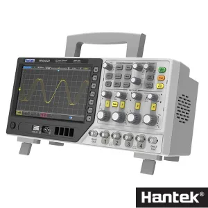
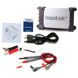
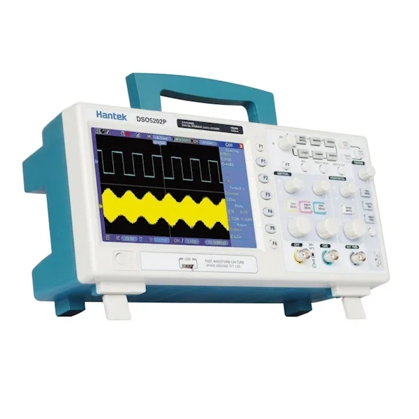
High-performance laboratory oscilloscope. It has a large 7″ colour TFT display with 64,000 colours, two channels with 200 MHz bandwidth, sampling rate (real time): 1 GS/s, record length up to 40 KB, multiple automatic measurements, built-in FFT (Fast Fourier Transform) function, several trigger modes (edge/pulse width/line selectable video/slop/overtime etc), software for real-time analysis on a PC, USB host port. The software lets you export the screens as Bitmap files, print them, save them in .wfm format and open them again. Box contents: oscilloscope, CD with software and manual (in English), 2 x 200 MHz probes, USB cable.
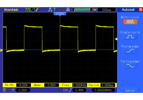
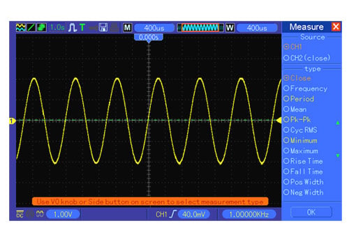
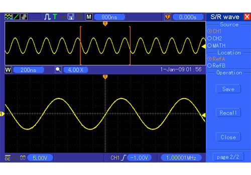
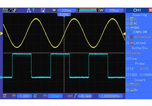
Screenshots of the “Digital Scope” software and of the oscilloscope

Technical features
  • 7″ TFT display, 64,000 colours (resolution: 800×480)
  • Built-in FFT (Fast Fourier Transform) function.
  • Software for real-time analysis on a PC
  • USB host port.
  • Multiple automatic measurements
  • Four maths functions, including FF
  • Box contents: oscilloscope, CD with software and manual (in English), 2 x 200 MHz probes, USB cable.
Technical specifications
  • Inputs
  • Horizontal
    – SEC/DIV Range: 2 ns/div to 40 s/div
    – Sampling rate and delay time accuracy: ± 50 ppm
    – Position Range: 2 ns/div to 10 ns/div; (-4div x s/div) to 20 ms
    – Delta Time measurement accuracy (full bandwidth): Single-shot, Normal mode:± (1 sample interval +100ppm × reading + 0.6ns); >16 averages:± (1 sample interval + 100ppm × reading + 0.4ns); Sample interval = s/div ÷ 200
  • Vertical
    – Vertical resolution: 8-bit resolution, all channels sampled simultaneously
    – Position Range: 2 mV / div a 200 mV / div, ±2V / 200 mV / div a 5V / div, ±50V
    – Rise Time at BNC (typical): 1.8 ns
    – Analogue bandwidth in normal and average mode at BNC or probe, DC coupling: 2 mV / div a 20 mV / div, ±400 mV; 50 mV / div a 200 mV / div, ±2V 500 mV / div a 2V / div, ±40V; 5V / div, ±50V
    – Math: +, -, *, /, FFT
    – FFT: Windows: Hanning, Flatop, Rectangular, Bartlett, Blackman; 1024 sample point
    – Bandwidth limit: 20 MHz
    – Low Frequency Response (-3db): = 10 Hz at BNC
    – DC gain accuracy: ± 3% for Normal or Average acquisition mode, 5V / div to 10 mV / div; ± 4% for Normal or Average acquisition mode, 5 mV / div to 2 mV / div
    – DC measurement accuracy, Average acquisition mode: when the vertical offset is zero and N = 16: ± (3% × reading + 0.1div +1mV) only 10mV / div or higher is selected; When the vertical offset is not zero and N = 16: ± [3% × (reading + vertical position) + 1% of vertical position + 0.2div]; Add 2mV for settings from 2 mV / div to 200mV / div; add 50 mV for settings from 200 mV / div to 5 V / div
    – Repeatability of voltage measurements
  • Trigger system
    – Trigger type: Edge, Video, Pulse, Slope, Over time, Alternative
    – Trigger source: CH1, CH2, EXT, EXT/5, AC Line
    – Trigger modes: Auto, Normal, single
    – Coupling type: DC, AC, Noise Reject, HF Reject, LF Reject
    – Trigger sensitivity (Edge Trigger Type): DC (CH1,CH2): 1div from DC to 10 MHz; 1.5div from 10 MHz to 100 MHz; 2div from 100 MHz to Full; DC(EXT): 200 mV from DC to 100 MHz; 350 mV from 100 MHz to 200 MHz; DC(EXT/5): 1V from DC to 100 MHz;1.75V from 100 MHz to 200 MHz; AC: attenuates signals below 10 Hz; HF Reject: attenuates signals above 80 kHz; LF Reject: attenuates signals below 150 kHz
    – Trigger Level Range: CH1/CH2: ±8 divisions from the centre of the screen; EXT: ±1.2V; EXT/5:±6V
    – Trigger Level accuracy (typical) The accuracy applies to signals with Rise and Fall times = 20 ns: CH1/CH2: 0.2div × volts/div within ± 4 divisions from the centre of the screen; EXT: ± (6% of setting + 40mV); EXT / 5: ± (6% of setting + 200mV);
    – 50% level (typical): works with input signals = 50 Hz
  • Measurement
    – Cursor measurement: voltage difference between cursors: difference between cursors Delta V / time: Delta T / Reciprocal of Delta T in Hertz (1/Delta T)
    – Automatic measurement: Frequency, Period, Mean, Peak-Peak, Cycle RMS, Minimum, Maximum, Rise time, Fall Time, +Pulse Width, -Pulse Width, Delay1-2Fall, +Duty, -Duty, Vbase, Vtop, Vmid, Vamp, Overshoot, Preshoot, Preiod Mean, Preiod RMS, FOVShoot, RPREShoot, BWIDTH, FRF, FFR, LRR, LRF, LFR, LFF
  • Display
    – 7″ TFT, 64,000 colours
    – Resolution: 800×480
    – Contrast: adjustable with a slider
  • Probe Compensator Output
    – Output voltage (typical): about 5 Vpp with a 1 Mohm load
    – Frequency (typical): 1 kHz
  • Power supply
    – Supply voltage: 120-240 Vac RMS (± 10%), 45 Hz to 66Hz
    – Power consumption: < 30W
    – Fuse: 2 A, T rating, 250 V
  • General
    – Operating temperature: 0°C to +50°C
    – Cooling method: convection
    – Humidity: (40°C or lower): = 90% relative humidity; (41°C to +50°C): = 60% relative humidity
    – Altitude: operating: below 3,000 m (10,000 feet); non-operating: below 15,000 m (50,000 feet)
    – Dimensions (mm): 313x142x108
    – Weight: 3.5 kg (with packaging); 2.08 kg (without packaging)
Download

Technical details

Maximum real-time sampling rate 1 GS/s
Bandwidth 200 MHz
Record length 40 KB
Trigger modes edge/pulse width/line selectable video/slop/overtime etc
Sampling rate (real time) 1 GS/s
Acquisition modes Normal, Peak and Average
Input coupling AC, DC, GND
Input impedance 1 Mohm ±2% 20pF±3pF
Probe attenuation 1X, 10X
Supported probe attenuation factor 1X, 10X, 100X, 1000X
Maximum input voltage CAT I and CAT II: 300 VRMS (10×), Installation Category
CAT III 150VRMS (1×)
Sample Rate Range 500 MS/s--1 GS/s
Waveform interpolation (sin x)/x

About us

Open-Electronics.org is the brainchild of a world leader in hobby electronics Futura Group srl. Open-Electronics.org is devoted to support development, hacking and playing with electronics: we share exciting open projects and create amazing products!

Open-Electronics.org is not just a container of ideas: it is also a web site lead by a team of engineers and geeks who will take part in the discussions and give support.

Our mission is to become a reference Open Source hacking site with ideas and feedback aimed to enrich the community.