
Dual-Mode Relay Timer
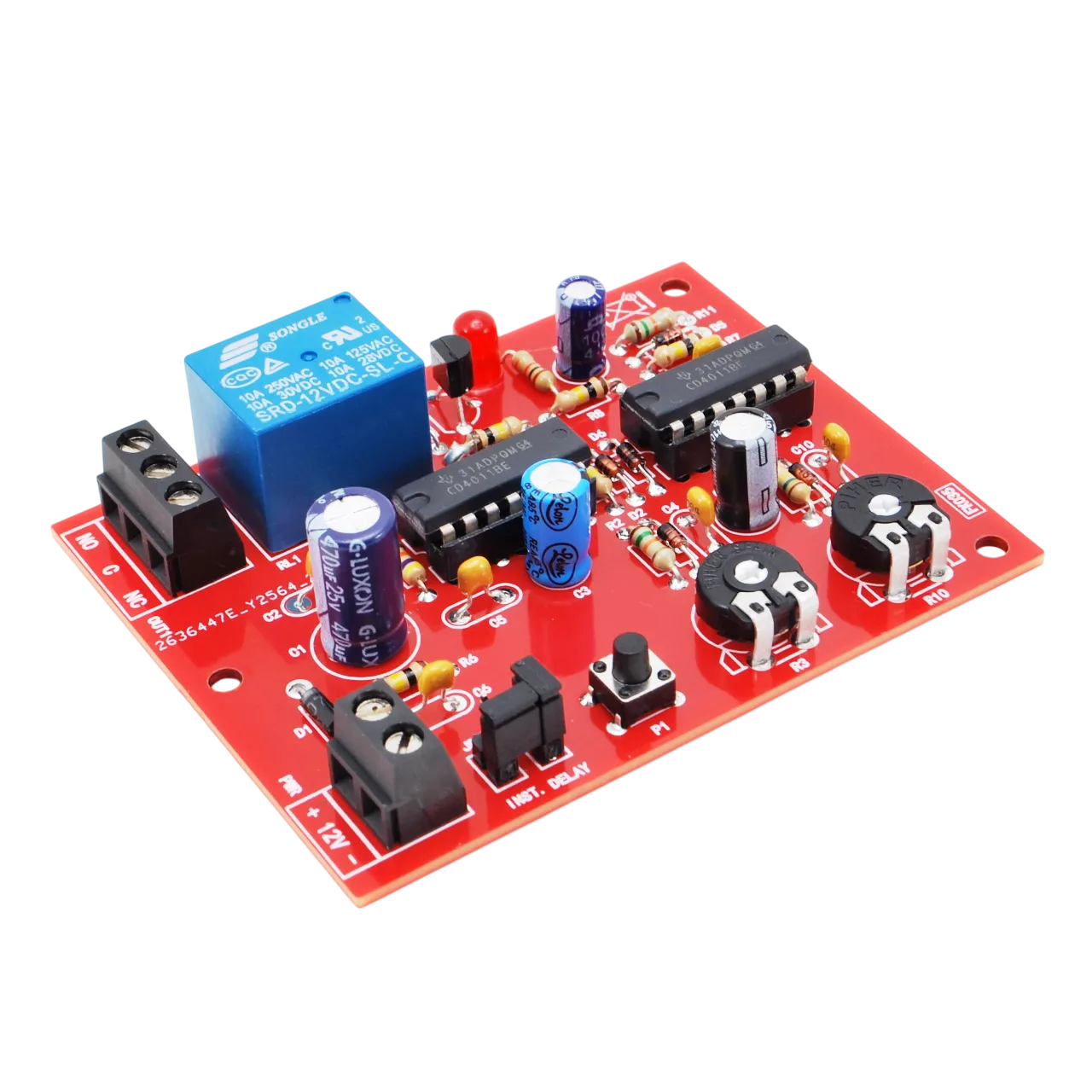
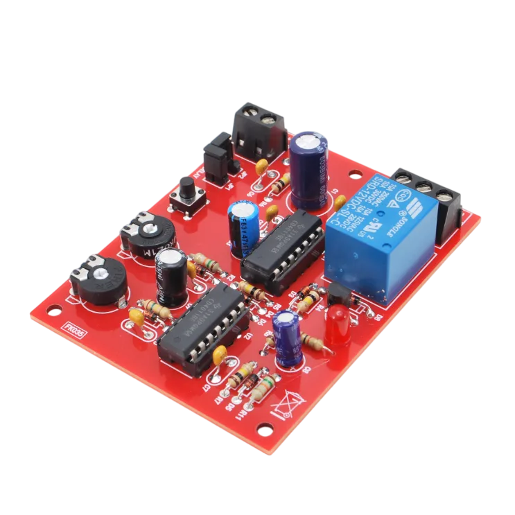
This versatile circuit lets you control electrical loads with two operating modes: delayed switch-on or switch-on when the button is released. It is the ideal project for anyone who loves electronics, since it is supplied as a kit of through-hole (THT) components ready to be soldered onto the PCB.
SKU 7100-FK035EAN 5410329216283Item type: Assembled, KitTimers & thermostats
Description
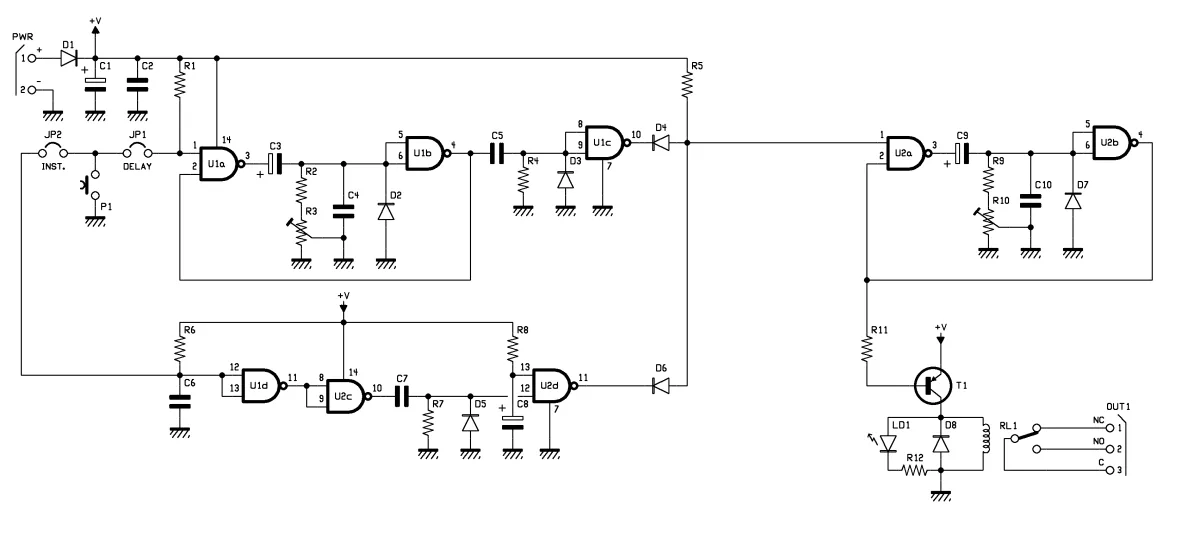
The Dual-Mode Timer is not just a simple timer, but a flexible tool that answers several control needs. Based on two CD4011B ICs (NAND gates), the circuit consists of two monostables working independently, so you can set the delay time and the activation time separately.
Operating modes selectable with jumpers (jumper):
DELAY mode (JP1 closed): when the button is pressed, the relay switches on only once the set delay interval has elapsed.
INST mode (JP2 closed): the relay switches on immediately when push-button P1 is released, providing a timed switch-off command.
| Circuit diagram |
 |
| Technical specifications |
|
Technical details
| Supply voltage | 12Vdc (ideal: 12Vdc to 14Vdc, regulated) |
|---|---|
| Current draw | About 80 mA |
| Output switch-on delay | From 0.5 to 22 seconds |
| Output activation time | From 1 to 100 seconds |
| Output rating | 250VAC/1A |
| PCB dimensions | 78 x 61 mm |
Related products
-
 Timers & thermostats
 -
 Timers & thermostats
 -
 Timers & thermostats
 -
 Timers & thermostats
 -
 Weather stations & clocks
 -
 Timers & thermostats
 -
 Timers & thermostats
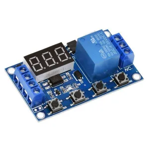
Timer from 0.1 second to 999 minutes with trigger and micro USB – assembled
€12.30excl. VAT€15.00incl. VAT -
 Other home products