
Antennino: the low-cost board for building remote sensors and actuators
SKU 7305-ANTENNINOEAN 8219671095549Item type: AssembledArduino compatible
Description
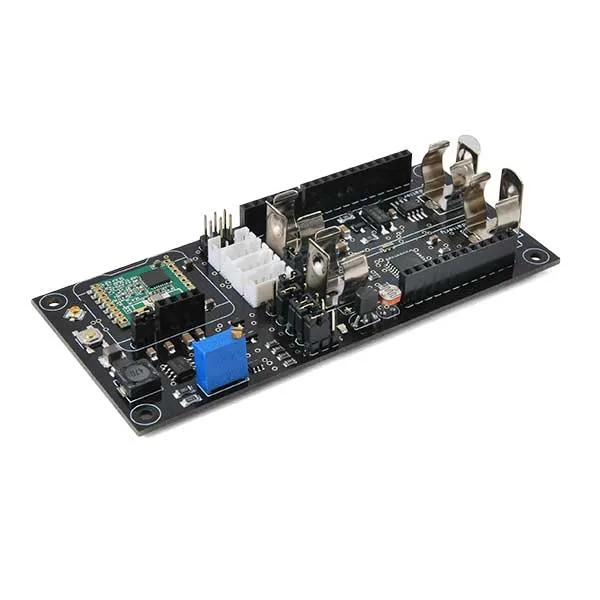
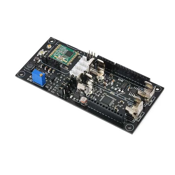
Antennino (the name Antennino is a combination of Antenna and Arduino) is a low-cost, low-power board based on the Atmel chip, therefore 100% compatible with the traditional Arduino IDE. The board integrates sensors and communication buses to acquire external information, as well as a wireless link to communicate with the outside world. Depending on how it is equipped, it can function both as a remote module and as an information collector (gateway).
The heart of Antennino is an ATmega328P microcontroller (the P indicates that it is a chip that adopts PicoPower technology, essential for the energy management desired in the project). Communication with the outside world occurs via an RFM69 transceiver module (www.hoperf.com) operating in the 433 MHz frequency band and supporting AES hardware encryption.
On board Antennino, a Flash memory (AT25F512B – 512 Kbit) is provided, which can be used to store data related to sensor readings (Data Logger) or to implement wireless programming (OTA) of the Antennino module, a temperature sensor (DS18B20), and a photoresistor.
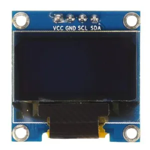
To facilitate the use of additional external sensors, four Grove connectors are present: one for serial, one for the I²C-Bus, one for general I/O, and one for analog input. Furthermore, Antennino is designed to host a small OLED display (sold separately – see related products), used when operating in gateway mode. Antennino has the same processor as the Arduino Uno and can therefore be used as a substitute for it, but given the wireless vocation of our module, the main use is to create remote sensors or actuators that can exchange information with a gateway. We could create temperature sensors, light sensors, alarm sensors for doors and windows, vibration sensors, remote actuators to control a device, etc.
Antennino is supplied with the bootloader already preloaded.
Regarding power supply options, the possibilities are:
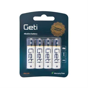
• power Antennino via two standard 1.5V alkaline AA batteries or 1.2V rechargeable ones (battery clips are already on the PCB);
• power Antennino via an external voltage of 3.6÷12 V;
• power Antennino directly with a voltage of 3.3V, bypassing all regulators on the board.
In the latter case, remember to absolutely not exceed 3.3V, otherwise you will damage the microcontroller and the various chips connected to it.
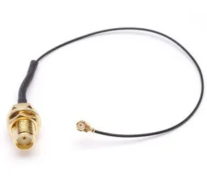
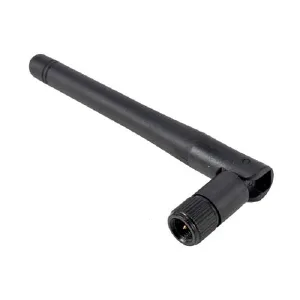
N.B. the 433 MHz antenna with SMA connector, the SMA-UFL adapter, the OLED display, and the batteries are not included; see related products.
Low Power Management via Libraries
Normally, when using a PicoPower type microcontroller, management of its low-power mode is done through specific libraries to include in the firmware. There are several depth levels of low-power mode, and in the deepest one the chip is like hibernating and can only be awakened by an external hardware interrupt. But clearly, if we wanted our remote sensor to send us periodic reports, this solution would not be feasible. A slightly less deep mode is, precisely, the one used when the microcontroller needs to wake up periodically on its own from the sleep state and perform some task, then go back to “sleep”.
Normally, the timer that wakes the microcontroller at regular intervals is implemented via an internal timer in the microcontroller, so it is not placed in a complete low-power state, but the one referred to by the acronym WDT (Watch Dog Timer) is left active. Obviously, the fact that there is a Timer and it is active comes at the cost of a small but not negligible current consumption of a few μA. An alternative is the one adopted in Antennino, where we use an external interrupt manager to wake the microcontroller. This concept will be extended by examining the circuit schematic.
Low Power Management via External Timer
A peculiarity of Antennino is the ability to exploit the potential of the TPL5110 chip (Texas Instruments), which is practically a digital timer with an intervention interval in the range of 100 ms÷7,200 s (2 hours), which in standby mode absorbs about 35 nA (you read correctly: only 35 billionths of an ampere) and allows controlling the power line via a P-MOS, excluding everything downstream. In this case, therefore, the consumption reduction strategy is entirely delegated to the TPL5110 chip. The chip has an input pin (DONE) that can receive feedback from the microcontroller to immediately deactivate the power supply if the operations that needed to be processed have been completed. Additionally, there is another input pin (DELAY/M_DRV) that allows forcing the TPL5110 to wake up early before the natural expiration of the set timing; this allows receiving an interrupt from an external source, handling its requests, then sending a DONE command to the TPL5110 and immediately returning to LowPower mode, deactivating everything except the TPL5110.
THE RFM69 MODULE
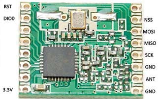
The wireless module used in Antennino, free to use provided transmissions are relatively short, works at a frequency of 433 MHz. For our application it is fine, as the gateway and remote module will only communicate to exchange information about sensor status.
In the latest versions of the RFM69 transceiver libraries, the ability to self-regulate the transmission power level has been introduced via a feature called Automatic Transmission Control (ATC), which allows further reducing the consumption of the Antennino module during transmission, automatically negotiating the minimum power necessary for data exchange. The SPI protocol is used (serial MISO, MOSI, SCK, RST), a Chip Select pin (NSS), and a pin (DIO0) for Interrupt notification to the microcontroller, plus naturally, the power supply and the pin for connecting the external antenna.
Technical specifications
- ATmega328P processor
- RFM69 433 MHz transceiver module
- AT25F512B Flash memory – 512-Kbit
- Power supply:
– via two standard 1.5V alkaline AA batteries or 1.2V rechargeable ones (battery clips are already on the PCB)
– via an external voltage of 3.6÷12 V
– directly with a voltage of 3.3V, bypassing all regulators on the board
In the latter case, remember to absolutely not exceed 3.3V, otherwise you will damage the microcontroller and the various chips connected to it
Discover the projects made with Antennino!
Documentation and useful links
Technical details
| Dimensions (mm) | 109x50x19 |
|---|---|
| GitHub | Examples and libraries |
You may also like…
-
 GPS
GPS -
 RF antennas
 -
 Non-rechargeable batteries
 -
 Interface converters
 -
 Displays
Related products
-
 Arduino
 -
 Control electronics
 -
 Arduino compatible
 -
 Displays
 -
 Arduino compatible
 -
 Development systems
 -
 Arduino
 -
Sale!
 Arduino compatible