
Ethernet Shield for Arduino – Soldering Kit Version
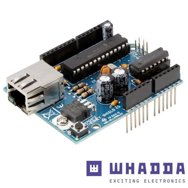
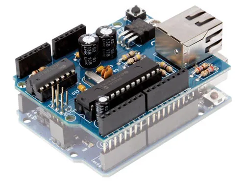
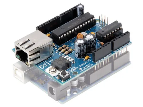
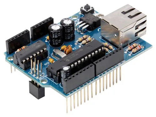
Ethernet shield for Arduino in soldering kit version. Allows you to set up the Arduino board as a simple web server and connect to the LAN/web.
SKU 8220-KA04EAN 5410329556488Item type: Kit, Shields & add-onsArduino, Arduino compatible
Description
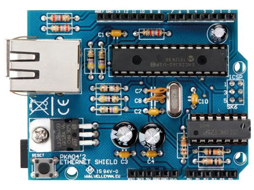
The shield is based on the ENC28J60, a Microchip microcontroller that handles both the interface with Arduino and data conversion according to the Ethernet protocol. The microcontroller contains a complete 10BaseT Ethernet interface, compliant with the IEEE 802.3 standard, and can be interfaced via an SPI bus (which it implements) configurable for a maximum clock of 20 MHz. It uses the ICSP instead of the side I/O lines to make the shield hardware-compatible with Arduino Duemilanove, UNO, and Mega. The digital lines D10 and D2 of Arduino also manage the Ethernet micro, respectively for controlling the CS (Chip Select, active low) and reading the INT. The Ethernet functionality allows for numerous networking applications such as remote control of systems and devices, home automation management of homes and other places, web access for downloading or publishing data, and much more; the ease of finding and integrating open-source Ethernet libraries into the Arduino IDE does the rest.
Power is taken from Arduino via the 5V and Vin contacts: the former provides the stabilized 5 volts to the circuit points that require them to operate (essentially the 74HC125 and the pull-up resistors on the reset and Chip Select lines), while the latter powers the integrated regulator U2, which derives the stabilized 3.3 volts needed to power the microcontroller and the coupling circuits inside the RJ45 jack.
The ENC28J60 Microcontroller
The ENC28J60 contains a complete 10BaseT Ethernet interface, compliant with the IEEE 802.3 standard, and can be interfaced via an SPI bus configurable for a maximum clock of 20 MHz. The component integrates the MAC controller, has an 8 kB Transmit/Receive Packet Dual Port Buffer, and a circular FIFO managed at the hardware level; it also allows programming of data retransmission in case of collision.
For the physical transceiver (PHY), an output shaping filter and the implementation of Loopback mode are provided.
The MAC controller supports Unicast, Multicast, and Broadcast packets, has a programmable pattern of 64 bytes within a user-allowed margin, and provides programmable wake-up for various packet formats (Magic Packet, Unicast, Multicast, Broadcast).
In the shield circuit, we see that the microcontroller does everything on its own and only needs a standard RJ45 jack with integrated LEDs, filters, and Ethernet line transformers, and a level adapter for its SPI interface, which in our case is needed to communicate with Arduino; more precisely, communication and management of the ENC28J60 occur via the SPI-Bus lines, which in the schematic connect to the contacts grouped under the ICSP.
The latter is the connector used in Arduino UNO and Duemilanove, as well as Arduino Mega, for In-Circuit Serial Programming (ICSP), i.e., in-circuit programming of the ATmega microcontroller (typically allowing the bootloader to be loaded into virgin micros); in our case, the sketch uses them to manage the Ethernet interface implemented by the Microchip micro.
We chose to use the ICSP instead of the side I/O lines to make the shield hardware-compatible with as many Arduino modules as possible, namely Arduino Duemilanove, UNO, and Mega; if we had used the side connectors, we would have made the shield usable only on Arduino Duemilanove and UNO, because on the Arduino Mega the contacts are arranged differently, as the latter has and makes accessible externally many more I/Os than the others. Instead, by using the ICSP, which is arranged identically, we can achieve compatibility with all three models.
Of the ICSP connector, MISO is the data output of the slave device, i.e., the ENC28J60, and the input of Arduino, while MOSI is the opposite, i.e., it brings to the ENC28J60 the data generated by Arduino; SCK is the clock that paces bidirectional communication on the SPI bus, and RESET is the reset line, to which a button is also connected that allows resetting the Ethernet interface manually when needed.
The digital lines D10 and D2 of Arduino also manage the Ethernet micro, respectively for controlling the /CS (Chip Select, active low) and reading the INT, whose state is read through U3a (74HC125). The latter, like U3b (74HC125), serves to adapt the logic levels at which U1 operates (which are 0/3.3 V) to those of Arduino (0/5 V).
The Network Travels… on the Network
To have an Internet connection in various points of the house, there are two solutions: a wired LAN or a wireless network; the former requires a series of cables around or the creation of wall traces, while the latter, besides posing security issues, might not provide the necessary coverage in multi-story houses.
For some time now, a third possibility has loomed on the horizon: PowerLine LAN. In practice, it is a system using carrier waves that allows creating a LAN using the 220-volt electrical wiring of the house, naturally without getting a shock!
This technology is based on “homeplug” devices, which are Ethernet transceivers with a coupling transformer to the power line (they are sold in pairs for a few tens of euros): you just plug one device into the power outlet closest to the router you use for Internet and the other into any outlet in the room where you want to connect with your computer.
Each adapter has an RJ45 jack to connect the LAN cable and can be connected to various devices, even just to create a generic local network to make a PC and a printer or other devices communicate.
PowerLine LAN can also be used in combination with other networks, obviously also with wireless ones, since the adapters essentially act as bridges between networks. Today, the technology can offer adapters capable of exceeding 100 Mbps.
Ethernet Sketch…
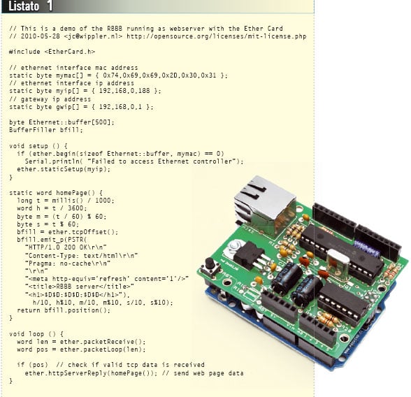
To use the Ethernet connectivity, upload the sketch you need to Arduino, remembering that from our site WWW.ELETTRONICAIN.IT you can download the specific library for managing the Microchip ENC28J60 and therefore our shield. The original library from which we derived the one we offer on our website can be downloaded from https://github.com/jcw/ethercard; from our site you can download the same library, but with a greater number of application examples.
In Listing 1 you will find an example sketch that allows you to create a Web Server; in particular, the web page displayed by our system will show the time, in hours, minutes, and seconds, elapsed since the Arduino was powered on.
Additional Information
- The product is a soldering kit
- The Arduino board is not included
- The assembled version is also available, code 8220-VMA04
Documentation and Useful Links
You may also like…
-
 Arduino
 -
 Arduino
Related products
-
 Arduino
 -
 Control electronics
 -
 Arduino compatible
 -
 Displays
 -
 Arduino compatible
 -
 Development systems
 -
 Arduino
 -
Sale!
 Arduino compatible