
Programmable timed coin acceptor
SKU 7100-FT1344KEAN 8219671092579Item type: Assembled, KitTimers & thermostats
Description
|
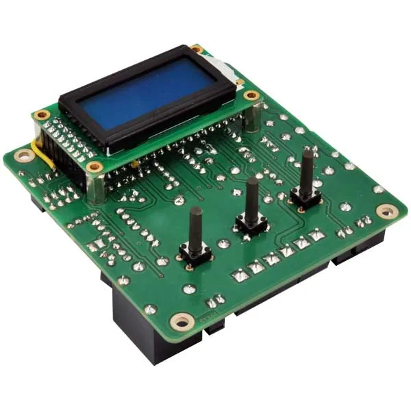
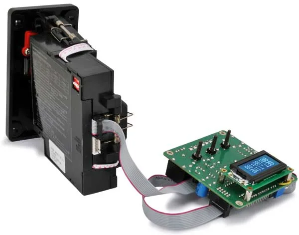
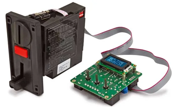
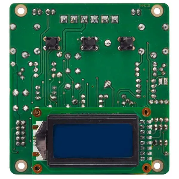
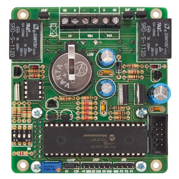
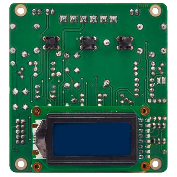
Set made up of an electronic board (solder-it-yourself kit) and a programmable electronic coin acceptor. It gives timed access to paid services such as games, showers, hair dryers and dispensers of all kinds, through a coin counter and a display interface. The board is run by a specially programmed Microchip PIC18F46K20 microcontroller and carries an 8-character, two-line LCD, 3 pushbuttons, a 4-way dip-switch and a configuration jumper. The board also reads the state of the open-collector outputs on the coin acceptor and switches the two on-board relays accordingly; in short, it is the interface between the user and the coin acceptor. The kit also includes the GETTON1 coin acceptor |
 |
| The coin acceptor |
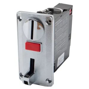
| The coin acceptor is the key part, because it counts the money and, through its two interfaces, reports the coins that have been inserted. Before it can be used properly it has to be taught to recognise the coins; for that, on its left-hand side there are two pushbuttons and a small 7-segment display that let you program the coins as you like. On the top there is a dip-switch that sets how it is used: in our case dip 1 must be ON and the others OFF. The first thing to do is to select parallel communication mode, because the coin acceptor leaves the factory set to serial mode (the procedure is explained in these pages). |
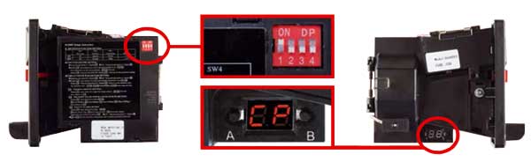 |
| In parallel mode each of the six outputs (one per storable group) produces a pulse of programmable length, so the length you want has to be set, which in our case is 100 ms. That done, the coin acceptor has to be programmed to recognise the coins: hold button “A” down until “CP” appears, then press button “A” once and “C1” appears (it means coin 1, the first coin, which is 5 cents); the same procedure is repeated for all the other coins, that is Group C2: €0.10, Group C3: €0.20, Group C4: €0.50, Group C5: €1.00 and Group C6: €2.00. Once programmed, the coin acceptor is connected to the control board with the ribbon cable that carries the parallel interface signals. |
| The user interface |
|
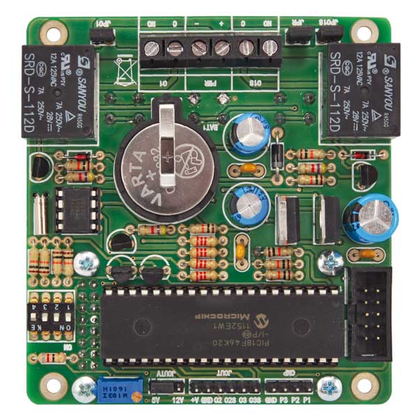
The 4-way dipswitch sets: coin accumulation, end-of-credit buzzer, anti black-out function.
|
  |
|
Jumper JPR selects the operating mode; closed, it enables programming mode, while open it selects normal operation.
The control board also carries other connectors and jumpers that can come in useful. For example jumper JPO1, or JPO1S, brings 12V (tapped before the supply protection diode) straight to contact “C” of the relay, so a load that runs on 12V can be Once the settings have been made, jumper JPR can be opened so the user cannot get into the settings by accident. |
| Board technical specifications |
|
| The enclosure for the kit |
|
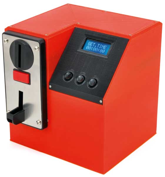
You can print the case on your own 3D printer using the STL files supplied, or you can order it, choosing the material and the colour from the options available. Please note: printing takes 2 days, so the order will be shipped as soon as the printed part is ready. |
 |
| Documentation and useful links |
Technical details
| Power supply | 12 Vdc / 700 mA |
|---|---|
| Output ratings (load and buzzer) | 12A / 28Vdc-125 Vac, 7A / 250Vac |
| Microcontroller | Microchip PIC18F46K20 |
| Backup battery for the RTC | Yes |
| Output activation time | 00:00:00 – 23:59:59 |
| Buzzer time | 10s – 50s |
You may also like…
-
 Other security
Related products
-
 Timers & thermostats
 -
 Timers & thermostats
 -
 Timers & thermostats
 -
 Timers & thermostats
 -
 Weather stations & clocks
 -
 Timers & thermostats
 -
 Timers & thermostats
Timer from 0.1 second to 999 minutes with trigger and micro USB – assembled
€12.30excl. VAT€15.00incl. VAT -
 Other home products