
Octopus – 16 I/O Shield – kit
SKU 7305-OCTOPUSEAN 8219671076555Item type: Kit, Robotics & gaming, Shields & add-onsArduino, Arduino compatible
Description
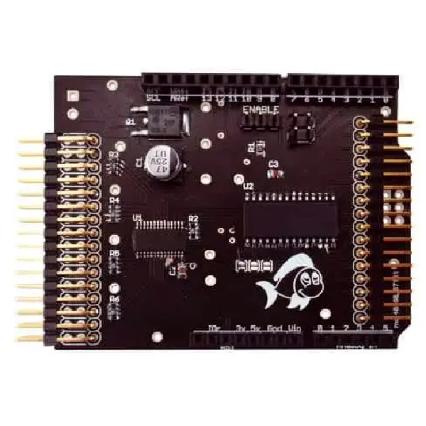
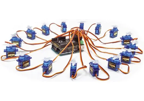
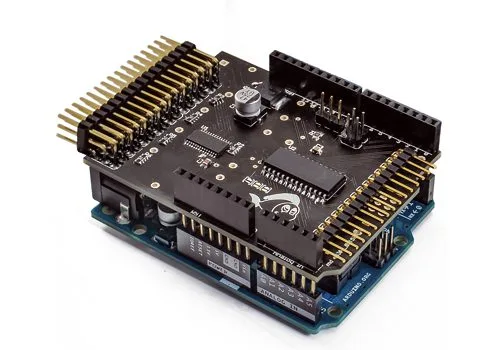
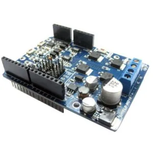
Expansion shield compatible with the various Arduino boards and with our Fishino UNO which, without practically engaging hardware resources, provides as many as 16 PWM outputs and 16 additional digital I/Os. Not only that, the boards can be stacked up to a maximum of 8, allowing you to manage with Arduino up to 128 digital I/Os and 128 additional PWM outputs; all made completely transparent to the user through a purpose-built library.
The product is supplied fully assembled as far as the SMD part is concerned, while only the connectors towards Arduino and towards external devices will remain to be soldered.
N.B. Arduino/Fishino and RC servos are not included (see related products).
Why it was made
However practical and capable of realizing countless applications, Arduino and compatible boards have two limitations: relatively small program memory and a limited number of available outputs, especially I/Os to which a PWM signal can be assigned. For example, an Arduino/Fishino UNO has only six PWM outputs and, unless the relative signals are generated via software (with considerable processor load), it allows driving a single driver and therefore a single power RGBW LED, or alternatively six monochromatic LEDs.
The same limitation emerges when you want to drive more than 6 servomotors with the same boards; building a robot like a “hexapod”, which requires as many as 12 servos, proves problematic, if not impossible. Digital inputs and outputs are also limited; again speaking of Arduino boards, we have a total of 13 digital I/Os and 6 analog inputs, also usable as digital; they would seem abundant, if it weren’t that many of these are used for on-board peripherals or by expansion shields. In practice, when building a project with an Ethernet/WiFi shield, an SD memory, and that needs the serial output and some analog inputs, only six digital I/Os remain available, which are often insufficient for medium-complexity projects.
The Library
As already mentioned, for this board we have created a dedicated software library, named Octopus, with some features that make its use very simple. The first interesting feature of the library can be seen from the lines of the include file (Octopus.h):
#define Octopus __octopus()
OctopusClass &__octopus();
and from the lines of the source file (Octopus.cpp):
OctopusClass &__octopus()
{
static OctopusClass octo;
return octo;
}
This apparently strange way of using the Octopus variable allows overcoming one of the problems of C++, namely the initialization of global variables which does not happen in a predetermined order but is random, and is performed when the sketch is loaded. In our case, having to initialize the I²C interface with the instructions:
Wire.begin();
Wire.setClock(400000);
before using the library, it is impossible to create the static Octopus variable at program load time, since the Wire interface is not yet initialized at that moment.
The chosen solution instead allows the variable to be created on first use, and therefore after having correctly initialized the I²C-Bus interface; this allowed us to create code that, without any additional program line, is able to count and correctly initialize all connected Octopus shields and automatically number their outputs in order of I²C address. For example, if we apply two shields to our Arduino, we will have 32 digital I/Os, numbered from 0 to 31, and 32 PWMs, also numbered from 0 to 31.
The library provides two functions that allow knowing the number of connected boards and the number of available I/Os and PWMs:
// return number of boards founduint8_t getNumBoards(void) const;
// return number of available I/Ouint8_t getNumIO(void) const;
As mentioned earlier, the PWM frequency is unique for each board, therefore for each group of 16 PWM outputs; it can be set via the following two functions, the first board by board and the second for all connected boards with a single command:
// set pwm frequency for a single connected board
// valid values 24 Hz…1526 Hzvoid setPWMFreq(uint8_t board, uint16_t freq);
// set pwm frequency for ALL connected boardsvoid setPWMFreq(uint16_t freq);
In the first, you must indicate the board number (ranging from 0 to Octopus.getNumBoards()) and the PWM frequency, from 24 Hz to 1,526 Hz; in the second, it is sufficient to indicate the frequency and all boards will be set to it. At power-on, the default frequency is 200 Hz, suitable for servos but also for LEDs. The value of the PWM outputs can be set, similarly to the Arduino libraries, via the following function:
// pwm output
void analogWrite(uint8_t port, uint16_t val, bool invert = false);
For example, to set output 30 (the third from last of the second connected board) to 50% of the maximum value, you must write Octopus.analogWrite(30, 2048);The third optional parameter, invert, is useful when connecting LEDs at the output using the outputs in open collector mode and connecting their anodes to the positive; in this case you need an inverted output (the longer it stays high, the less current flows through the LED) and therefore it is necessary to set the parameter
to true to obtain increasing brightness with the val value. As you have certainly noticed, the PWM value, unlike Arduino outputs, is 16-bit, of which 12 are used, thus allowing an intensity variation of 4,096 levels instead of Arduino’s 256; this allows, for example, much more gradual control of the light intensity emitted by LEDs connected to the board. On the other hand, you must remember this when setting the value, since a number equal to 255, which on Arduino corresponds to maximum intensity, here corresponds to a rather low value (255/4,096 of the maximum). For managing digital I/Os, the library provides the following functions, practically identical to those
of the standard libraries, except for the fact that you can use a very large number of ports:
// digital I/Ovoid pinMode(uint8_t port, uint8_t mode);bool digitalRead(uint8_t port);void digitalWrite(uint8_t port, bool value);
// read/write all digital pins of given board at onceuint16_t digitalReadAll(uint8_t board);void digitalWriteAll(uint8_t board, uint16_t val);
The last two functions allow reading and writing all digital ports of a board in one go, via a 16-bit variable; this is very convenient when you need to modify or read the digital ports very quickly. At the time of writing this article, the library (downloadable from our site www.elettronicain.it together with the project files) is being completed, and the functions for interrupts and for changing the mode of the PWM outputs (open drain/totem pole) have yet to be completed.
A Test Sketch
To conclude, we present a simple sketch that allows displaying a luminous “tail” using 16 LEDs connected to the PWM outputs (Listing 1).
The code initializes the serial interface, prints a message, initializes the I²C, prints the number of detected boards and, using the first of them (PWM outputs 0 to 15), creates a sort of luminous ‘snake’ using 16 LEDs.
The brightness values of the ‘snake’ are pre-calculated in the setup and placed in a table containing 16 values; depending on the starting point of the table (variable ‘i’ in the loop) the ‘snake’s head’ is in a different point, thus creating the desired visual effect.
As you can see, apart from having to put ‘Octopus.’ in front of the analogWrite() commands, the use is practically identical to the native Arduino library. The only noteworthy thing is the calculation of the brightness values, done here with a second-order polynomial to create a wave effect; other methods are possible with trigonometric functions or simply with a linear variation on which you can experiment; for example:
for(int k = 0; k < 16; k++)
sinTable[k] = 4096 * sin(M_PI / 16 * k);
for a sinusoidal trend, or
for(int k = 0; k < 16; k++)
if(k <= 8)
sinTable[k] = 4096 * (double)k / 8;
else
sinTable[k] = 4096 * (double)(15 – k)
/ 8;
for a bilinear trend.
We conclude here the description of our Octopus board; you can now experiment with different light effects using, for example, the Colibrì driver presented in the previous issue of Elettronica In.
Documentation and useful links
You may also like…
-
 Actuators
 -
 Actuators
 -
 Actuators
 -
 Arduino
 -
 Robots
 -
 Actuators
 -
 Actuators
 -
 Robots
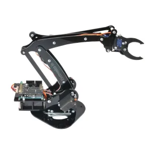
Articulated plexiglass robotic arm with 4 degrees of freedom and rotating base
€72.95excl. VAT€89.00incl. VAT
Related products
-
 Arduino
 -
 Control electronics
 -
 Arduino compatible
 -
 Displays
 -
 Arduino compatible
 -
 Development systems
 -
 Arduino
 -
Sale!
 Arduino compatible