
GSM/GPRS Shield for Arduino
SKU 8190-GSMGPRSSHIELDV2EAN 8219671003346Item type: Assembled, Kit, Shields & add-onsArduino, Arduino compatible
Description
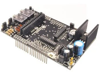
Shield for Arduino that can accommodate the GSM/GPRS & GPS modules we offer, shown in the related products. The module, properly controlled via a serial interface and a UART for connection management, allows voice calls, sending SMS, or making connections to the Internet. The availability of new support libraries for software development allows great flexibility in configuring the modules and developing voice, data, and WEB-based applications. With simple calls to high-level functions, it is possible, for example, to read a received SMS or start a call and perform all other operations done by a normal mobile phone.
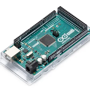
The board, compatible with Arduino Duemilanove, Arduino UNO, Arduino MEGA, etc., has two jacks for analog audio flow. Thanks to a microphone and an earpiece with 3.5 mm jacks (standard computer headset is sufficient), you can make a full voice call. In case of an incoming call, a ringtone will be heard through the headphones to alert you. The shield includes the high-capacity capacitor dedicated to the RTC (Real Time Clock), usable exclusively on modules that have this function.
The capacitor keeps the time updated even without power. The entire circuit operates with a supply voltage of 12 Vdc provided directly from the Arduino board. During the heaviest current consumption operations, such as GPRS usage, the module draws current peaks of about 1A, so the power source must be able to supply that current. The shield has a connector for an external lithium battery, rechargeable only with SIM908, as the module integrates a dedicated charging circuit. The voltage needed for battery charging is taken directly from the Arduino board (from the Vin pin).
The maximum footprint of the shield is 100 x 57 mm. The package does not include the GSM module, antenna, and battery, which are sold separately. The board is designed to accommodate one of the following modules related to this board (the choice depends on your needs). The battery to be used must be rechargeable lithium with a nominal voltage of 3.7V and a 3-way connector with 1.25mm pitch.
Note: Not compatible with code TDGGSM_A7682E
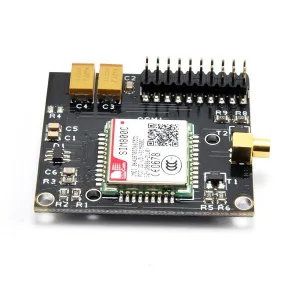
GSM/GPRS & GPS Shield V2 with the FT1308M module (miniaturized cell phone module with SIM800C)
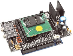
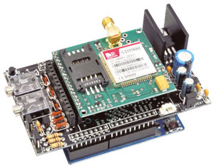
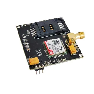
GSM/GPRS & GPS Shield V2 with the TDGGSM_800F or TDGGSM_800C module (GSM module with SIM800F)
Configuration
To preserve compatibility with the Arduino Mega, the communication mode with the SIM900/SIM800 (hardware serial, using pins 0 and 1 of the Arduino Uno, or software serial using pins 2 and 3 instead) is set via jumper, but there is also the possibility of using pins of your choice via a simple connection.
Also to preserve maximum flexibility and customization, the board is equipped with solder pads on the back (Fig. 2), which allow you to make connections to bring the data flow control signals (CTS, RTS) or alert signals for incoming calls or unread SMS (RI) to the Arduino digital inputs. It is therefore possible to disable these connections, saving the number of inputs or outputs used, while still having the option, if needed, to use them as you see fit by making a jumper.
Fig. 3 shows the presence of two pin strip connectors on the top. These additional connections allow the shield to be used with the new compact modules of the SIM900 and SIM908, which have a different pinout aimed at saving space. The new SIM908 module, also from SIMCom, features a 42-channel GPS locator with an accuracy of less than 2.5 meters. Using the BAT/VEXT jumper (Fig. 4) you can set the shield’s power source: place the jumper on VEXT to power the device via the Arduino board, or on BAT if using an external rechargeable battery. To allow charging of the latter, you must close the jumper marked CHRG (Fig. 5) located near the CRTC capacitor.
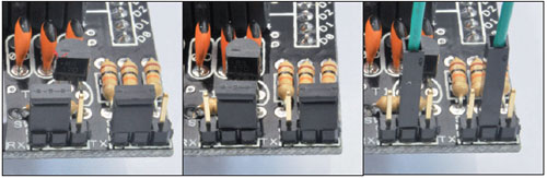
Fig. 1 – On the left the configuration for software serial, in the center hardware, and on the right customized.
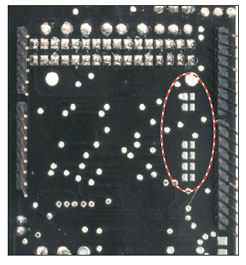
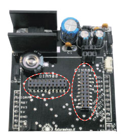
Fig. 2 – Detail of the SIM900 control signal traces, with the possibility of bringing them to Arduino inputs via a simple solder. Fig. 3 – Strips for connecting the new modules that equip the SIMCom family chips in compact version.
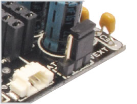
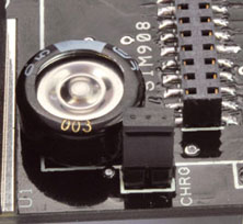
Fig. 4 – Jumper for selecting the power source (BAT = battery power; VEXT = power via Arduino board). Fig. 5 – CHRG jumper. Closing this jumper, the system charges the external battery if connected to the shield.
You may also like…
-
 GSM/GPRS
 -
 Arduino
 -
 GSM/GPRS
 -
 GSM/GPRS
 -
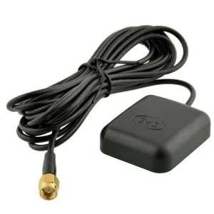 GPS
GPS -
 GSM/GPRS
 -
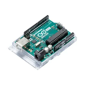 Arduino
Related products
-
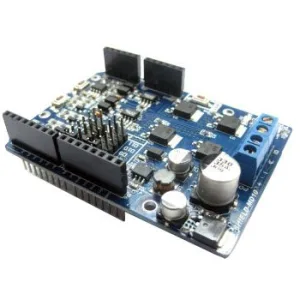 Arduino
 -
 Control electronics
 -
 Arduino compatible
 -
 Displays
 -
 Arduino compatible
 -
 Development systems
 -
 Arduino
 -
Sale!
 Arduino compatible